


Injection Mold Components: Main Parts and What Each One Does
Injection mold components include the core, cavity, runner system, cooling channels, ejector system, guide pillars, and support plates. Each part controls a different stage of the molding cycle, from shaping and cooling to alignment and ejection. Understanding how these systems work together helps manufacturers reduce defects, improve cycle time, and choose the right mold design for production needs.
Injection molds look simple from the outside, but inside they contain multiple precision systems working together under high pressure and temperature. A small issue in cooling, alignment, or ejection can affect part quality, cycle time, and mold lifespan. This guide explains the main mold components, what each one does, and how they influence real production performance.
What are the main injection mold components?
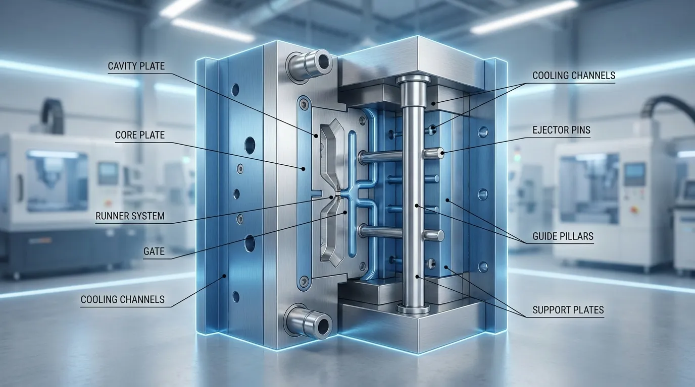
Injection mold components work together to guide molten plastic, shape the part, cool it evenly, and eject it safely after solidification. The main systems include the core and cavity, runner and gate system, cooling channels, ejector system, guiding components, and mold base structure.
An injection mold is built from several connected systems instead of a single block of steel. Each system handles a specific function during the molding cycle. Some parts shape the plastic, others manage heat, and others control movement and alignment.
The mold base supports the entire structure and holds the internal components in position. Inside the mold, molten plastic enters through the feed system, fills the cavity, cools down, and is ejected after solidification. According to the injection molding process overview, molds typically contain separate injection and ejection sides that open and close during production.
| Component System | Main Function | Common Production Risk |
|---|---|---|
| Core and cavity | Shape the plastic part | Dimensional errors |
| Runner and gate system | Guide molten plastic | Short shots or imbalance |
| Cooling channels | Remove heat | Warpage |
| Ejection system | Remove finished part | Surface marks |
| Guide pillars and bushings | Maintain alignment | Flash |
| Support plates | Handle pressure loads | Mold wear |
If you want a broader overview of how molds operate inside the full production cycle, this plastic injection mold process guide explains the complete workflow.
What is the difference between the core and cavity?
The cavity forms the external shape of the plastic part, while the core creates the internal geometry. Together, these two mold halves define the final dimensions, wall thickness, and surface quality of the molded component.
The cavity side usually stays on the fixed half of the mold. It shapes the outer surface that customers see after molding. Surface texture, cosmetic finish, and visible details often come from the cavity surface.
The core side usually sits on the moving half of the mold. It creates internal features such as holes, ribs, slots, and hollow sections. During ejection, the molded part normally stays attached to the core side because shrinkage tightens around the core.
| Feature | Cavity | Core |
|---|---|---|
| Main role | Forms outside surface | Forms internal geometry |
| Mold position | Fixed side | Moving side |
| Surface focus | Cosmetic finish | Structural detail |
| Ejection side | Usually releases part | Usually holds part |
Poor machining or wear in either section can create dimensional variation. Even slight misalignment between the core and cavity may cause flash around the parting line. This becomes more critical in tight-tolerance applications such as medical housings or precision electronics.
For a deeper look at overall mold architecture, see these mold structure basics.
How does the feed system move plastic through the mold?
The feed system guides molten plastic from the injection machine into the mold cavity. It includes the sprue bushing, runners, and gates, all of which control pressure, material distribution, and filling consistency.
The feed system acts like a controlled pathway for molten resin. Plastic first enters through the sprue bushing, then travels through runners before passing into the cavity through the gate. Every section affects filling speed, pressure, and balance.
What does a sprue bushing do?
The sprue bushing connects the molding machine nozzle to the mold. It handles the first stage of material transfer and directs molten plastic into the runner system. Poor sprue design can create leakage, pressure loss, or uneven filling.
Why runner balance matters in multi-cavity molds
Runner layout becomes more important in multi-cavity molds because every cavity must fill evenly. If one runner path is longer than another, cavities may fill at different speeds. This can create dimensional variation between parts.
A packaging mold with uneven runner lengths may produce one cavity with excess flash while another shows short shots. Balanced runner systems reduce this risk and improve production consistency.
The gate controls how molten plastic enters the cavity. Smaller gates reduce visible marks, but they can restrict flow in thicker parts. Larger gates improve filling but may increase trimming work after molding.
More cooling channels do not automatically improve molding quality. Poorly balanced cooling and feed layouts can still create uneven shrinkage and warpage even when flow rates appear acceptable.
For a broader explanation of filling and molding stages, this injection molding workflow covers the full production sequence.
Why is the cooling system critical in injection molding?
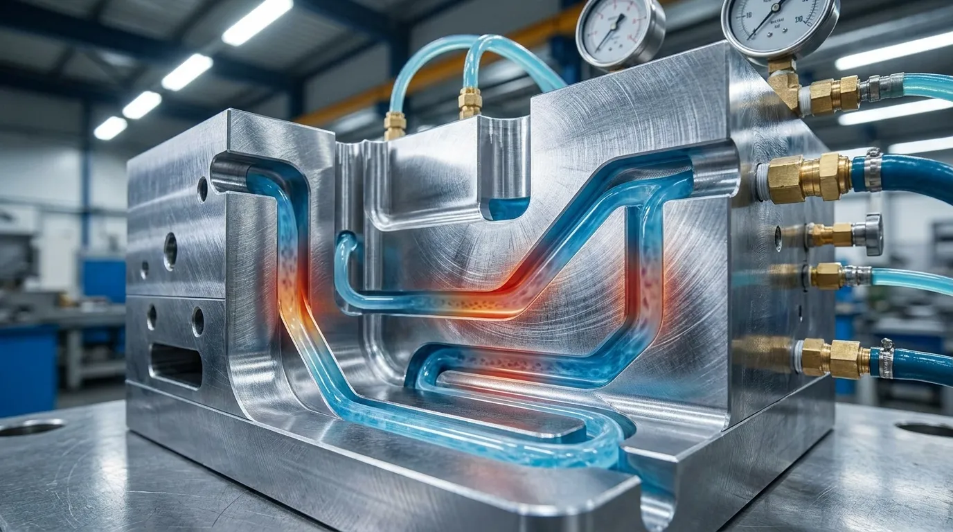
Cooling channels remove heat from the mold after plastic fills the cavity. Proper cooling improves cycle time, dimensional stability, and surface quality while reducing warpage and uneven shrinkage.
Cooling often controls most of the molding cycle time. If heat stays trapped inside the mold too long, production slows down and part dimensions become less stable. According to RapidDirect’s mold component guide, cooling systems also help reduce mold wear by controlling thermal stress.
Cooling channels are drilled through the mold base around the cavity and core. Water or coolant circulates through these channels to remove heat evenly. Placement matters because uneven cooling creates uneven shrinkage.
A medical housing mold may develop warpage if cooling channels sit too far from one side of the cavity. One side cools faster while the opposite side continues shrinking, causing the finished part to twist slightly after ejection.
| If This Happens | Cooling Problem | Typical Result |
|---|---|---|
| One area cools slower | Poor channel placement | Warpage |
| Cooling is uneven | Temperature imbalance | Shrinkage variation |
| Mold stays too hot | Slow heat removal | Longer cycle time |
| Hot spots form | Limited coolant flow | Surface defects |
More cooling channels are not always better. Excessive channel density can weaken steel sections or create uneven thermal behavior. In many cases, balanced cooling design matters more than maximum cooling volume.
Applications with tight tolerances often require advanced thermal control. These precision molding applications show where cooling consistency becomes critical.
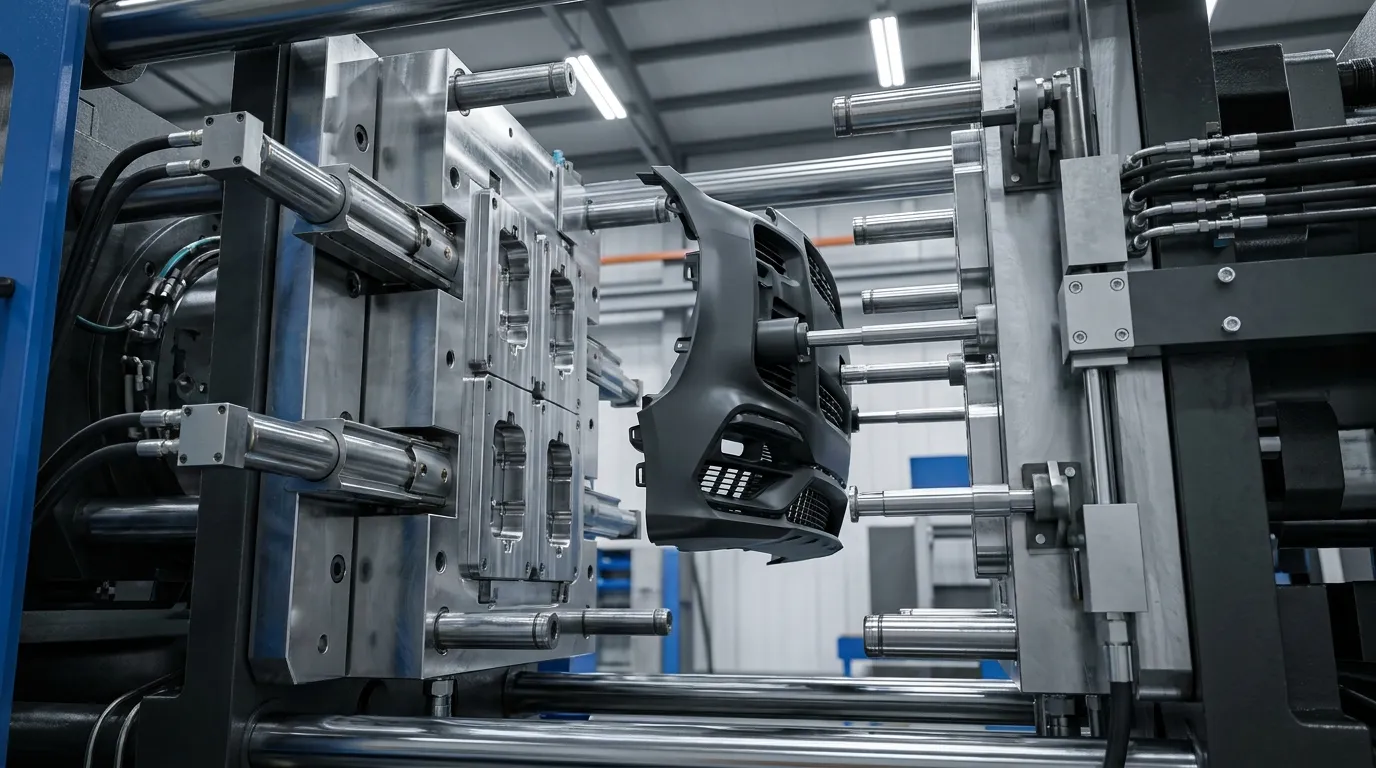
What does the ejection system do?
The ejection system removes the molded part from the core side after cooling. Ejector pins are the most common method, but sleeves and stripper plates may be used for delicate or deep components.
After the mold opens, the molded part usually remains attached to the core side. The ejection system pushes the part free without damaging surfaces or deforming thin sections.
Ejector pins are the most widely used method because they are simple and cost-effective. Pins push directly against selected points on the part surface. Poor placement, however, can leave visible pin marks or create stress points.
A high-volume packaging mold may show ejector pin wear after extended production cycles. Over time, repeated movement creates friction and surface wear that transfers onto cosmetic areas of the molded part.
- Ejector pins
- Ejector sleeves
- Stripper plates
- Return pins
- Ejector plates
Slides are not always the best solution for difficult ejection. Straight-pull designs are often easier to maintain and reduce downtime risk when geometry allows simpler mold movement.
For additional details on ejector hardware and layout, these ejector system components explain the full structure.
How do guide pillars and support plates keep molds aligned?
Guide pillars and bushings keep the mold halves aligned during every production cycle. Proper alignment prevents flash, uneven wear, dimensional variation, and premature mold damage.
Guide pillars and bushings control mold alignment during opening and closing. These components ensure the core and cavity meet in the correct position under clamping pressure. Even small alignment errors can affect part quality.
A consumer electronics mold may begin producing flash after guide bushings wear down. The mold halves no longer close perfectly, allowing molten plastic to escape along the parting line.
Support plates handle the heavy mechanical loads generated during injection. Without adequate support, mold plates may flex under pressure, especially in large or multi-cavity molds.
- Guide pillars
- Guide bushings
- Support plates
- Clamping plates
- Spacer blocks
According to FirstMold’s injection mold guide, guiding structures play a major role in maintaining molding accuracy and protecting mold life.
For a closer look at structural mold systems, review these mold base systems.
What are slides and lifters used for in complex molds?
Slides and lifters allow molds to release parts with undercuts or side features that cannot eject straight out of the cavity. These moving components increase mold complexity but are essential for many functional plastic parts.
Some plastic parts contain side holes, clips, hooks, or undercuts that prevent straight ejection. Slides and lifters solve this problem by moving sideways or at an angle during mold opening.
When a mold needs side actions
An automotive clip with locking tabs may require side actions because the undercut geometry traps the part inside the mold. Without slides, the part could not eject without damage.
Slides move perpendicular to the mold opening direction, while lifters move upward at an angle during ejection. According to the injection molding reference, these systems are commonly used for undercut release in complex parts.
These systems increase tooling cost because they require additional machining, wear surfaces, and moving assemblies. They also add maintenance requirements during long production runs.
Multi-cavity molds are not always the best option when slides are involved. Complex side actions increase alignment sensitivity and raise downtime risk if maintenance intervals are ignored.
You can see examples of these features in complex molded parts used across automotive and industrial products.
Which injection mold components affect part quality the most?
Part quality depends heavily on cooling balance, venting efficiency, alignment precision, and controlled ejection. Even small design errors in these systems can create flash, sink marks, burn marks, or dimensional instability.
Several mold systems directly influence cosmetic quality and dimensional accuracy. Problems often appear when one system works correctly while another becomes unstable.
Poor venting is a common example. Trapped air inside the cavity can create burn marks or incomplete filling. According to Elastron’s molding defect guide, weak venting is one of the major causes of gas-related molding defects.
| Defect | Related Component | Likely Cause | Common Correction |
|---|---|---|---|
| Flash | Guide system | Misalignment | Replace worn bushings |
| Warpage | Cooling system | Uneven cooling | Rebalance channels |
| Burn marks | Venting system | Trapped gas | Improve venting |
| Pin marks | Ejection system | Poor pin placement | Adjust ejector layout |
| Dimensional variation | Runner system | Unbalanced filling | Correct runner lengths |
A multi-cavity mold with uneven runners may fill some cavities faster than others. One part may shrink differently even when machine settings stay unchanged. Balanced flow design reduces this variation.
Cooling balance matters more than cooling quantity. Adding more channels without proper placement can create temperature differences that increase warpage instead of reducing it.
For a broader explanation of molding consistency and defect prevention, this molding quality factors guide covers the full production picture.
How do mold components influence tooling cost and maintenance?
Complex mold components increase tooling cost because they require tighter machining tolerances, additional assemblies, and more maintenance planning. Cooling layouts, slides, multi-cavity systems, and wear surfaces all affect long-term production cost.
Simple two-plate molds are easier to machine and maintain. Once slides, lifters, and advanced cooling systems are added, manufacturing complexity rises quickly. More moving parts also increase inspection and replacement requirements during production.
| Component Feature | Cost Impact | Maintenance Impact |
|---|---|---|
| Multi-cavity layout | Higher machining precision | More balancing checks |
| Slides and lifters | Additional moving assemblies | Higher wear risk |
| Advanced cooling | Complex drilling and routing | More cleaning needs |
| Hot runner systems | Higher initial tooling cost | Electrical maintenance |
Wear components usually require the most attention. Gates, ejector pins, guide bushings, and moving slide surfaces experience repeated friction during production cycles.
A simpler mold is sometimes the safer long-term choice. Lower-volume projects may not benefit from highly complex tooling if maintenance downtime offsets production speed gains.
According to EWMFG’s mold component guide, mold structure and system complexity directly affect durability and operational efficiency.
Getting the Next Step Right
Understanding injection mold components helps buyers and engineers make better tooling decisions before production begins. Small details such as cooling layout, runner balance, or guide wear can affect cycle time, part quality, and maintenance cost far more than many first-time buyers expect.
If you're evaluating a new mold design, focus on how the systems work together instead of looking at components individually. A balanced mold usually performs better, lasts longer, and creates fewer production problems over time. For a broader view of tooling strategy and mold engineering, reviewing a complete molding guide can help connect these systems to the full manufacturing process.
Frequently Asked Questions
What are the main components of an injection mold?
The main injection mold components include the core, cavity, sprue bushing, runner system, gates, cooling channels, ejector system, guide pillars, and support plates. Each system controls a different stage of the molding cycle, from filling and cooling to alignment and part removal.
What does an ejector pin do in injection molding?
An ejector pin pushes the cooled plastic part off the core side after molding is complete. Poor ejector pin placement can leave visible marks or damage delicate surfaces during removal.
Why are cooling channels important in injection molds?
Cooling channels remove heat from the mold to control cycle time and part stability. Uneven cooling can cause warpage, shrinkage differences, and inconsistent dimensions across molded parts.
What is the difference between the core and cavity?
The cavity forms the outside shape of the plastic part, while the core forms the internal geometry. These two mold surfaces close together to create the final molded structure.
What causes flash in injection molding?
Flash usually happens when mold halves do not align correctly or when pressure escapes at the parting line. Worn guide components and poor clamping conditions are common causes of this defect.
What are slides and lifters used for?
Slides and lifters help release parts with undercuts or side features that cannot eject straight out of the mold. They allow more complex geometries but increase tooling complexity and maintenance needs.
Which mold components wear out the fastest?
Gates, ejector pins, slides, guide bushings, and high-friction surfaces usually wear faster than structural plates. Wear rates increase in high-volume production and abrasive material applications.
Share:


Written By miashuvo
NEWS
GET SERVICE
With quality parts to meet every budget and friendly staff trained to make your visit informative and hassle free.