



Perforation Punch Pin Design for Repeated Small-Hole Patterns
Perforation punch pin design is not simply a matter of choosing a small diameter and a hard material. A reliable design must coordinate the hole pattern, sheet material, punch geometry, support system, combined cutting force, die clearance, slug path, and maintenance method.
The challenge becomes greater as hole diameter decreases or more holes are punched during each stroke. A long, unsupported tip may deflect. A dense cluster can exceed press capacity or distort the sheet. Small slugs may clog the die or return to the work surface. The punch therefore has to be designed as part of the complete cutting system.
For broader information about punches, stripper systems, guide elements, and other tooling parts, see the die components guide (inferred). This guide focuses specifically on punch pins used for repeated small-hole patterns.
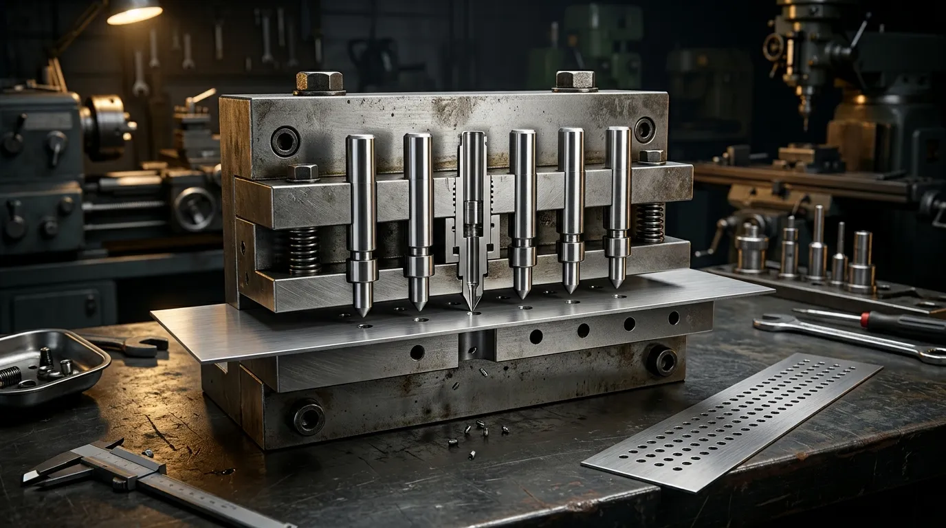
What Must Be Designed Together in a Perforation Punching System?
A perforation punch pin forms one part of a load path that extends through the tool:
- The cutting tip enters the sheet.
- The punch shank transfers the cutting load upward.
- The punch plate locates and retains the pin.
- The backing plate supports the punch against axial reaction.
- The stripper controls the sheet and may guide the punch near its tip.
- The die opening provides the opposing cutting edge.
- The slug passes through the die relief and exits the tool.
A weakness in any one part can affect the entire operation. A strong punch material will not prevent failure if the working tip is too long, the stripper allows lateral movement, or the die opening is misaligned. A correctly sized pin can still produce unstable results if several tips create excessive combined force or if the slug path becomes blocked.
This is why perforation tooling should not be treated as an isolated component-selection exercise. General die construction and die-type decisions are covered more broadly in the punching dies guide. Here, the design starts with the repeated hole pattern and works inward toward the punch pin.
Define the Hole Pattern and Sheet Requirements Before Designing the Pin
The working diameter is only one input. Before selecting a pin architecture or material, define the conditions that control the cutting operation.
The design package should include:
- Sheet material and condition
- Nominal sheet thickness and thickness tolerance
- Hole diameter, shape, and dimensional tolerance
- Hole pitch in each direction
- Remaining material between adjacent holes
- Pattern arrangement, including aligned or staggered rows
- Required open area
- Burr direction and allowable burr height
- Sheet-flatness requirements
- Expected production volume
- Available press and station capacity
- Lubrication and cleanliness requirements
- Planned sharpening and replacement method
These inputs are connected. Changing the sheet thickness affects cutting force, slug geometry, practical hole size, and die clearance. Reducing hole pitch leaves less material between adjacent openings and may weaken both the sheet and the die. Increasing the number of tips raises the combined cut perimeter and total force.
Hole Size, Material, and Thickness Set the First Feasibility Check
A small hole is more difficult to punch when its diameter approaches or falls below the sheet thickness. The exact practical limit depends on the work material, punch material, guidance, alignment, tool construction, and required hole quality.
A hard or high-strength sheet generally creates greater cutting load than a softer material of the same thickness. A small punch cross-section must carry that load without bending, chipping, or breaking. Guided tooling may support a more demanding diameter-to-thickness relationship than a long, non-guided punch, but guidance does not eliminate the need for sufficient punch strength.
Technical references such as MISUMI’s guidance on small-diameter hole punching emphasize short working sections, stepped support, and controlled slug removal. Supplier ratios can be useful for an early feasibility check, but they should not be treated as universal design limits.
Pitch, Remaining Web, and Flatness Define the Pattern-Level Risk
Hole pitch is the centre-to-centre distance between adjacent perforations. The remaining web, sometimes called the bridge, is the material left between their edges.
A pattern may contain individually feasible holes but still be difficult to manufacture if the web becomes too narrow. Dense perforations can:
- Reduce local sheet stiffness
- Weaken the die material between openings
- Increase the risk of hole interaction
- Produce sheet stretch or waviness
- Create oil-canning across a larger panel
- Concentrate cutting load in one region of the tool
Aligned rows and staggered rows do not distribute load in the same way. A staggered pattern may improve open-area distribution or reduce direct alignment of weak sections, but it does not automatically solve distortion. The finished panel’s flatness requirement must be considered with the complete punching sequence.
Choose the Punch Pin Architecture That Supports the Small Working Tip
A perforation pin normally contains several functional regions:
- The working tip that creates the hole
- A transition or shoulder behind the tip
- A larger shank that transfers and supports the load
- A retention feature that locates the punch in the punch plate
- An adjustment or regrinding allowance where required
The small working portion should be only as long as the operation needs. Extra unsupported length increases sensitivity to lateral movement and bending. The required length must still allow suitable penetration, stripper guidance, withdrawal, and future sharpening.
Straight, Stepped, and Multi-Step Pins Serve Different Section Sizes
| Pin architecture | Typical design logic | Main advantage | Main limitation |
|---|---|---|---|
| Straight pin | Working section and shank have the same or similar cross-section | Simple geometry and manufacture | A very small full-length section may lack stiffness |
| Stepped pin | Small working tip is supported by a larger shank | Better support behind the cutting section | Shoulder position and transition require careful design |
| Multi-step pin | Several transitions connect a small tip to a much larger body | More gradual change between widely different sections | More complex geometry and inspection |
MISUMI’s discussion of hole-punching punch design distinguishes straight, stepped, and multi-step punches according to the strength and size of the functional section.
A stepped punch is often considered when the required hole is too small for a long straight pin to remain sufficiently rigid. The larger shank provides support, while the smaller section performs the cut. The transition should transfer load without creating an unnecessarily sharp stress concentration.
Working Length and Transition Geometry Control Deflection and Stress
Two punches with the same tip diameter can behave very differently if one has a much longer unsupported working section.
As the slender section becomes longer, the pin becomes more vulnerable to:
- Lateral deflection
- Misalignment with the die opening
- Uneven side wear
- Chipping at the cutting edge
- Fatigue breakage
- Bending during stripping
The transition behind the working tip also matters. An abrupt reduction in section can create a highly stressed area. A better-supported transition distributes the load into the larger shank while preserving the required access to the sheet and stripper.
There is no single universal working-length ratio for every material and application. The final geometry must account for penetration, sheet thickness, stripper position, guidance length, regrinding allowance, and the actual load on the tip.
Guide, Retain, and Back the Punch Through the Full Stroke
Small punches require both axial and lateral support.
The punch plate retains and locates the shank. The backing plate supports the punch against cutting reaction. The stripper controls the sheet during withdrawal and may guide the punch close to the cutting region. These elements must remain aligned with the die opening.
Even a correctly dimensioned pin can fail if the support system allows side loading.
Stripper Guidance Limits Punch Wandering Near the Cutting Tip
A stripper-guided punch passes through a controlled opening in the stripper plate before entering the sheet. This close support reduces the distance over which the small tip can move laterally.
MISUMI’s technical note on stripper guidance for hole-blanking punches explains that small punches are especially vulnerable to lateral movement. The stripper can reduce that movement, but only when the stripper itself moves accurately.
If the stripper tilts, shifts, or has excessive clearance, it may transfer error to the punch rather than correcting it. The stripper opening, punch shank, and die opening must therefore be treated as one alignment system.
Punch Plate and Backing Plate Complete the Axial Load Path
The punch plate positions the pin, but it may not provide sufficient resistance to concentrated axial load by itself. A small punch head or shank can create high local pressure behind the pin.
A backing plate spreads this reaction into a stronger supporting area. Without adequate backing, the punch may indent or sink into the holder, changing its working height and alignment.
MISUMI’s guidance on backing-plate design highlights this issue for punches with small supporting cross-sections.
The load path should remain flat, rigid, and correctly located. A hard punch placed against a weak or poorly supported holder can still lose position under repeated loading.
Match Pin Count and Pattern Arrangement to the Available Punching Force
A cluster punch produces several holes in one stroke. This can reduce the number of press cycles required, but the press must cut the combined perimeter of all engaged tips.
The total load is not determined by hole count alone. It depends on:
- Total engaged cut perimeter
- Sheet thickness
- Work-material shear resistance
- Number of tips cutting simultaneously
- Punch sharpness
- Die clearance
- Stripping conditions
- Tool and press efficiency
Adding more tips may increase output per stroke, but it also raises cutting load, slug volume, maintenance exposure, and the possibility of sheet distortion.
Estimate Force from Total Cut Perimeter, Not Hole Count Alone
A conceptual punching-force relationship is:
Punching force ≈ total cut perimeter × sheet thickness × material shear resistance
For a cluster, the total cut perimeter is the sum of the perimeters of all tips engaged during the same part of the stroke.
This means ten small round holes do not create the same load as ten slots with a much greater combined perimeter. Two patterns with similar open area may also require different force because their edge lengths differ.
Mate Precision’s cluster punching guidance uses total cutting perimeter as a central force-planning factor and recommends checking cluster load against the machine and station limits.
The calculation should be treated as an engineering estimate. The actual tool must also account for stripping force, load balance, press condition, and the manufacturer’s tooling limits.
Staggering and Load Distribution Can Reduce Pattern-Level Problems
If every adjacent tip enters the material at the same time, cutting load may be concentrated within a small area. This can increase peak force and stretch the sheet around the pattern.
Possible design responses include:
- Dividing the pattern across more than one station
- Using fewer active tips
- Arranging rows so that engagement is distributed
- Staggering tip lengths where the tooling system permits it
- Balancing the pattern around the tool centre
- Changing the punching sequence
These methods can reduce local concentration, but they may also add tool complexity or change the loading sequence. They must preserve the finished hole locations and part geometry.
Wilson Tool’s information on perforating with cluster tools also identifies sheet stretch and oil-canning as practical concerns in dense perforation work.
Coordinate Die Clearance with Slug Evacuation
The punch and die opening form one cutting pair. Clearance between them influences cutting load, fracture behaviour, burr formation, tool wear, and slug release.
Repeated small-hole patterns make waste handling especially important. A cluster with 20 tips creates 20 slugs during each complete punching cycle. Even when each slug is small, the cumulative waste flow can become substantial.
The die must provide:
- Suitable cutting clearance
- Adequate die land
- Relief below the cutting edge
- A continuous exit route
- Access for inspection and cleaning
- Protection against slug recirculation
Clearance Must Be Verified for the Material, Thickness, and Required Edge
Clearance is normally considered per side between the punch and die cutting edges. The appropriate value depends on the sheet material, thickness, required edge condition, punch condition, and tooling method.
Clearance that is too small may increase force and wear. Clearance that is too large may increase burrs, edge rollover, or dimensional variation. As the punch and die wear, effective clearance changes even if the original dimensions remain correct.
For this article, the important point is that the pin diameter cannot be finalized independently from the die opening. Exact clearance values require material- and application-specific calculation and validation.
Every Additional Hole Adds Another Slug That Must Exit Reliably
Small slugs can:
- Accumulate in restricted die passages
- Bridge across narrow relief sections
- Compact into a blockage
- Adhere to the punch face
- Return to the work surface
- Damage the sheet during a later stroke
The die relief should allow slugs to move away without trapping one another. Tool access should permit cleaning before debris raises the cutting load or damages the punch.
Slug pulling requires particular attention. A slug that follows the punch upward may be pressed back into the sheet or trapped between the tool and workpiece. Geometry, clearance, lubrication, surface condition, and waste-path design can all influence this behaviour.
Select Pin Material and Surface Treatment by the Expected Failure Mode
The hardest available punch material is not automatically the best choice. Material selection should respond to the dominant failure risk.
Common risks include:
- Abrasive wear
- Adhesive wear or galling
- Edge chipping
- Fatigue breakage
- Plastic deformation
- Impact from misalignment
- Corrosion or surface damage
A material that resists wear well may be less tolerant of shock or side loading. A tougher material may survive misalignment better but require more frequent sharpening.
Tool Steel, HSS, and Carbide Balance Wear and Toughness Differently
| Material family | Useful characteristics | Main design concern |
| Tool steel | Broad balance of toughness, wear resistance, heat treatment, and regrindability | Performance depends strongly on grade and heat treatment |
| High-speed or powder-metallurgy steel | Can provide higher wear resistance while retaining useful toughness | Cost and machining difficulty may increase |
| Carbide | High wear resistance and compressive strength | More sensitive to impact, chipping, and alignment errors |
Carbide may be suitable for stable, abrasive, high-volume applications, but it is not a universal solution for every small hole. A slender carbide tip exposed to side load or impact may chip where a tougher steel punch would survive.
The selection should consider the sheet material, working-tip diameter, unsupported length, guidance, lubrication, press condition, and previous failure history.
SunshinePro’s custom punch pin page lists SKH51, SKH9, DC53, ASP-grade materials, and carbide among its stated material options. Final suitability still has to be confirmed against the actual drawing and application.
Surface Finish, Coating, and Lubrication Address Surface Interaction
Surface finish influences friction, material pickup, release, and the condition of the substrate beneath a coating. A smoother working surface may help reduce adhesion in suitable applications, but finish alone cannot correct an unsupported tip or misaligned die.
Coatings such as TiN, TiCN, and DLC may be considered for selected wear or friction conditions. Their value depends on:
- Punch substrate
- Workpiece material
- Surface preparation
- Edge geometry
- Lubrication
- Temperature
- Impact and side loading
- Coating adhesion
A coating should not be used as a structural repair. It cannot compensate for excessive working length, poor stripper guidance, weak backing, or incorrect clearance.
Lubrication is also part of the system. It can reduce friction, adhesive wear, and stripping resistance, but the lubricant must be compatible with the work material, downstream process, and cleanliness requirements.
Design the Tool for Replacement, Sharpening, and Inspection
Perforation tooling should be serviceable before the first production run begins. A design that performs well initially but cannot be repaired economically may create unnecessary downtime later.
The maintenance plan should address:
- Individual pin replacement
- Spare-tip availability
- Sharpening allowance
- Length adjustment after regrinding
- Access to retained pins
- Tip identification
- Inspection points
- Replacement limits
Fixed Multi-Tip Tools and Replaceable Tips Create Different Maintenance Models
A fixed multi-tip punch may be compact and mechanically simple. If one tip is damaged, however, the repair may affect the complete tool.
Replaceable-tip systems allow individual punches to be changed without discarding the whole cluster body. Wilson Tool describes replaceable configurations among its perforation-tool options.
Replaceable tips are not suitable for every pattern. Very close spacing may leave insufficient room for individual retention features. The design must also provide access for removal, accurate location after replacement, and a practical spare-parts system.
The best configuration depends on pattern density, maintenance frequency, tool size, and the cost of replacing one damaged position compared with servicing the complete assembly.
Regrinding Changes More Than the Cutting Edge
Sharpening removes material from the cutting face. This changes the punch length and may alter penetration, adjustment, stripper relationship, or the available guided length.
After regrinding, inspect:
- Tip diameter or profile
- Cutting-edge condition
- Remaining working length
- Straightness
- Concentricity between tip and shank
- Transition condition
- Surface damage
- Retention feature
- Overall length or adjustment position
A pin should not remain in service merely because its edge can still be sharpened. If the remaining geometry no longer provides sufficient support or alignment, replacement may be safer than another regrind.
Diagnose Pattern Problems by Reviewing the Design Variable Behind Them
Production symptoms rarely identify one guaranteed root cause. They do indicate which design relationships should be checked first.
| Production symptom | Possible design causes | Items to review |
| Punch wandering or hole-position variation | Long unsupported tip, weak stripper guidance, misalignment | Working length, stripper clearance, plate alignment, concentricity |
| Repeated punch breakage | Excessive force, side loading, stress concentration, insufficient toughness | Tip length, transition, material, clearance, press alignment |
| Edge chipping | Brittle material, impact, poor edge condition, uneven contact | Material grade, heat treatment, punch face, alignment |
| Rapid burr growth | Punch or die wear, changing effective clearance | Cutting edges, die opening, sharpening interval |
| Galling or material pickup | Adhesive work material, poor finish, unsuitable lubrication | Surface finish, coating, lubricant, clearance |
| Slug pulling | Adhesion, unsuitable clearance, poor release conditions | Punch face, die opening, lubricant, slug path |
| Die blockage | Restricted relief or excessive slug accumulation | Die land, relief, exit path, cleaning access |
| Uneven holes across a cluster | Unbalanced load, different tip lengths, plate deflection | Tip projection, backing support, tool rigidity |
| Sheet waviness or oil-canning | Dense pattern, concentrated engagement, insufficient web | Pitch, pattern sequence, active tip count |
| Excessive press load | Too much simultaneous cut perimeter, dull edges, poor clearance | Pin count, cutting perimeter, material, edge condition |
For a broader review of fractured or chipped punches, see punch breakage in stamping dies. The focus here should remain on the design variables created by small diameters and repeated patterns.
Prepare a Supplier-Ready Drawing and RFQ Package
A supplier cannot evaluate a perforation application from the punch diameter alone. The same nominal pin may behave very differently in thin aluminium, high-strength steel, coated sheet, or a dense multi-tip cluster.
A useful RFQ package should include:
- Workpiece material and condition
- Nominal thickness and tolerance
- Hole shape, dimensions, and tolerances
- Full pattern drawing
- Pitch and remaining web
- Required burr direction
- Flatness or distortion requirement
- Single-tip or cluster-tool intention
- Working-tip diameter and length
- Shank dimensions
- Step and transition geometry
- Retention method
- Die-opening and clearance information, if already defined
- Press type and relevant capacity
- Production volume
- Lubrication conditions
- Current failure history for replacement projects
- Requested material and heat treatment
- Surface-finish or coating requirement
- Required inspection characteristics
- Regrinding and spare-pin strategy
- Drawing revision and acceptance criteria
Include the Pattern, Press, and Failure History—not Only the Pin Diameter
For a replacement project, provide the complete pattern and production context wherever possible. Useful supporting information may include:
- Photos of the worn or broken punch
- Images of the damaged sheet
- Location of failures within the pattern
- Current sharpening history
- Burr progression
- Slug-blockage evidence
- Press-load changes
- Existing punch and die dimensions
This information helps distinguish a material problem from a geometry, alignment, clearance, or waste-flow problem.
Confirm Manufacturing Scope and Acceptance Criteria Before Production
The RFQ should state whether the supplier is being asked to:
- Manufacture a pin to an approved drawing
- Review manufacturability of the pin geometry
- Recommend a material or coating
- Produce replacement pins from a sample
- Supply inspection documentation
- Participate in broader die or application design
These are different scopes of responsibility.
SunshinePro states that it produces custom punch pins from customer drawings and lists CNC machining, EDM, precision grinding, heat treatment, and optional coatings on the product page. Project-specific material, tolerance, finish, coating suitability, and inspection requirements should still be confirmed against the drawing.
For a technical review or quotation, provide the pattern drawing, sheet material and thickness, punch geometry, press information, and any current failure details through the SunshinePro contact page.
Share:


Written By Tonmoy
NEWS
GET SERVICE
With quality parts to meet every budget and friendly staff trained to make your visit informative and hassle free.
