



Punch Pin Inspection Checklist for Incoming and Routine QC
A punch pin inspection checklist should answer four questions: Is this the correct punch? Does it match the approved specification? Is it still fit for service? What action should follow the inspection?
This guide covers individual punch pins used in metal-stamping dies. Incoming QC verifies a newly supplied punch against the purchase order, drawing, revision, and required documentation. Routine QC checks whether a punch remains serviceable after production use, regrinding, a collision, or another abnormal event.
Punch pins work within a larger die system. Guides, bushings, retainers, stripper components, die clearance, and alignment can all influence punch condition. The broader roles of these components are covered in the die components guide (inferred). Here, the focus stays on inspecting and dispositioning the punch pin itself.
No universal tolerance, inspection interval, or wear limit applies to every punch pin. Acceptance must be based on the approved drawing, purchase specification, control plan, or another documented requirement.
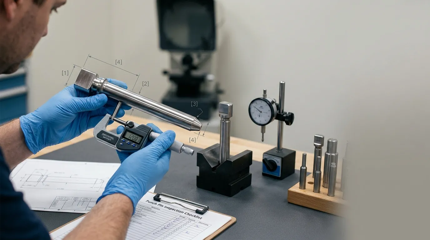
Incoming QC and Routine QC Check Different Risks
Incoming and routine inspection use many of the same instruments, but they answer different questions.
| Inspection stage | Main purpose | Typical checks | Main decision |
|---|---|---|---|
| Incoming QC | Confirm that the supplied punch matches the order and approved specification | Part identity, drawing revision, material or coating documents, visible damage, dimensions, geometry, inspection report | Accept, hold, return, or reject |
| Routine QC | Confirm that a used punch remains safe and functional | Edge wear, cracks, galling, dimensional change, runout, working length, production symptoms, regrind history | Return to service, monitor, regrind, replace, or investigate |
| Post-regrind inspection | Confirm that sharpening restored the edge without making other features unacceptable | Edge form, burr removal, overall length, working length, profile, surface condition | Release, rework, or replace |
| Post-event inspection | Check for hidden or visible damage after a jam, collision, misfeed, or nearby breakage | Cracks, bending, head damage, runout, seating surfaces, mating components | Quarantine, investigate, repair, or replace |
Incoming inspection should establish a reliable baseline. Recording the punch’s as-received dimensions and condition makes later wear easier to identify.
Routine inspection compares the current punch against that baseline and any approved service limits. A punch can remain within its original manufacturing tolerance yet show an abnormal wear trend. Conversely, a worn feature may still appear visually acceptable while no longer meeting the documented service requirement.
Prepare the Punch, Documents, and Measuring Equipment
Inspection should not begin with a caliper. It should begin with the correct documents, part identity, and measurement conditions.
- Confirm the inspection stage. Record whether the punch is incoming, in routine service, newly reground, or being checked after an abnormal event.
- Obtain the approved drawing. Verify the drawing number and revision before measuring anything. An accurate measurement against an obsolete revision is still an invalid inspection result.
- Review the purchase and quality requirements. Check the purchase order, control plan, approved sample, inspection-report requirement, and any requested material, heat-treatment, hardness, or coating documentation.
- Match the punch to its records. Confirm the part number, lot or serial number, quantity, material designation, coating designation, and any engraved identification.
- Inspect the packaging before cleaning. Record impact damage, corrosion, broken protective packaging, loose punches, or signs that sharp edges contacted each other during transport.
- Clean the punch carefully. Remove oil, dirt, chips, and transferred material without rounding the cutting edge or scratching a coated surface. Residue on a diameter or seating face can affect the measurement.
- Stabilize the part when tolerances are tight. A punch arriving from a hot production area, cold warehouse, or vehicle may need time to reach the inspection environment. Temperature differences can affect dimensional results.
- Verify the measuring equipment. Check instrument identification, calibration status, measuring range, resolution, contact condition, and cleanliness. Confirm that any V-block, center, fixture, or surface plate is also clean and suitable for the feature.
SunshinePro states that non-standard mold parts can be processed from customer drawings, while its punch-pin page lists diameter, length, head style, material grade, and coating as customizable characteristics. Those fields should therefore be treated as drawing- and order-specific requirements rather than assumed product defaults.
Resolve Conflicting or Missing Specifications Before Measurement
Do not select a tolerance from memory, an old inspection sheet, or a generic catalog.
Place the punch on hold when:
- the drawing revision does not match the purchase order;
- the inspection report refers to another part or lot;
- the drawing and purchase specification contain conflicting limits;
- the material or coating designation is missing;
- the required datum or measurement method is unclear;
- an approved deviation is mentioned but not supplied.
Obtain written clarification from the responsible engineer, customer, or supplier before assigning a pass or fail result. The controlling-document hierarchy should follow the customer’s quality system or contract rather than an informal assumption.
Inspect Every Punch Feature for Visible Damage
Visual inspection is the fastest way to find obvious defects, but it should follow a consistent feature-by-feature sequence.
Use clean lighting and suitable magnification. Rotate the punch and inspect the complete circumference rather than viewing only one side.
| Inspection zone | Conditions to check | Possible significance | Typical next action |
| Cutting edge and tip | Chipping, cracks, edge rounding, burrs, deformation, pickup | Loss of cutting quality, local overload, impact, wear, adhesive material transfer | Measure, quarantine, regrind, or replace |
| Shank or body | Scoring, galling, wear bands, corrosion, fretting, transferred material | Poor guidance, friction, misalignment, lubrication problem, incorrect fit | Clean, measure diameter/runout, inspect mating parts |
| Head and shoulder | Mushrooming, peening, cracks, uneven seating marks, deformation | Overload, incorrect seating, retainer problem, inadequate support | Quarantine and inspect retainer or seating condition |
| Transition radii | Cracks, grinding marks, abrupt surface changes | Stress concentration, grinding damage, fatigue initiation | Magnify, escalate, or replace |
| Coated surface | Peeling, flaking, scratches, discoloration, exposed substrate | Coating damage, friction, impact, corrosion, wear | Record location, assess function, seek engineering review |
| Identification marks | Missing or illegible part, lot, or serial information | Loss of traceability or risk of mixing revisions | Hold until identity is confirmed |
A small chip at the cutting edge is not equivalent to a superficial scratch on a non-working surface. The inspection record should state the defect location, approximate extent, and whether it affects a functional feature.
Cracks, severe deformation, or a damaged retention head generally justify immediate quarantine. Galling, pickup, or one-sided scoring may require inspection of the die system as well as the punch. Detailed causes of cracking and catastrophic failure belong in the guide to punch breakage in stamping dies.
What Visual Inspection Cannot Confirm
Visual inspection cannot reliably establish:
- exact body or tip diameter;
- overall or working length;
- straightness;
- runout, concentricity, or coaxiality;
- shaped-tip profile;
- numerical surface roughness;
- material grade;
- heat-treatment conformity;
- hardness;
- coating identity.
A punch may look undamaged but still be dimensionally out of tolerance. Material grade, hardness, and coating conformity may require traceable documentation or a specified test method.
Measure the Dimensions and Geometry That Control Fit and Function
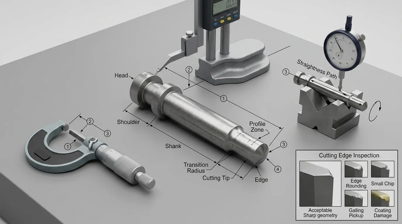
The approved drawing determines which dimensions and geometric controls must be inspected. Not every punch requires every measurement.
| Characteristic | Why it matters | Possible measurement method | Important limitation | Acceptance source |
| Body or shank diameter | Affects guidance, fit, retention, and alignment | Outside micrometer; suitable limit gauge | Contact location and taper must be considered | Drawing or fit specification |
| Tip diameter | Affects pierced feature size and punch-die relationship | Micrometer, specialized gauge, optical system | Small or delicate tips may not suit standard contacts | Drawing |
| Shaped tip profile | Controls non-round holes or formed geometry | Optical comparator, vision system, CMM | Requires correct datum alignment and profile interpretation | Drawing with profile requirement |
| Overall length | Supports identification, installation, and regrind tracking | Height gauge, micrometer, comparator, dedicated fixture | Seating faces must be clean and consistently referenced | Drawing |
| Working length or projection | Influences operating position and penetration | Height gauge, comparator, dedicated inspection fixture | Definition must match the drawing; do not borrow tablet-tooling terminology | Drawing or setup specification |
| Head diameter and thickness | Affects retention and seating | Micrometer, caliper for screening, comparator | Burrs or peening can distort contact | Drawing |
| Shoulder position | Influences seating and assembled projection | Height gauge, comparator, CMM | Datum setup must reproduce the drawing requirement | Drawing |
| Straightness | Detects bending or axis deviation | Indicator with suitable support, CMM, dedicated fixture | Support method and datum choice affect the result | Drawing or approved service limit |
| Circular or total runout | Shows rotational variation relative to a datum axis | Indicator with centers or V-block; CMM | “Runout” must match the exact drawing control | Drawing |
| Concentricity or coaxiality | Evaluates relationship between axes or features | CMM or approved specialized method | Do not substitute a simple runout check unless engineering approves it | Drawing |
| Perpendicularity | Affects seating or alignment of end faces and shoulders | Indicator, surface plate setup, CMM | Requires a valid datum reference | Drawing |
| Surface roughness | Can influence friction, fit, release, and galling | Surface roughness tester | Parameter, cutoff, direction, and location must be specified | Drawing or surface specification |
| Hardness | May confirm a heat-treatment requirement | Approved hardness test or supplier documentation | Test scale, location, surface condition, and indentation effect matter | Drawing or material specification |
Geometric terms should be interpreted according to the drawing standard in use. ISO 1101 defines geometrical tolerancing concepts in the ISO system, while ASME Y14.5 is widely used for US-oriented GD&T drawings.
A drawing that specifies runout should not be rewritten as concentricity during inspection. These controls describe different requirements and may require different measurement strategies.
SunshinePro’s tungsten-carbide punch page lists micrometer or caliper checks, projector measurement, and roughness testing for that product category. Those published methods show the types of inspection that may be relevant, but they do not prove that every punch or every order receives the same checks.
Choose the Instrument According to the Tolerance and Feature
Instrument choice should be based on the feature, tolerance, access, and required measurement confidence.
| Instrument | Best use | Main limitation |
| Micrometer | Accessible external diameters and thicknesses | Contact geometry may not suit small, tapered, delicate, or irregular features |
| Caliper | Identification, broad dimensions, and screening | Resolution and operator influence may be unsuitable for tight tolerances |
| Height gauge and surface plate | Axial dimensions, shoulder positions, and comparative height checks | Requires controlled seating and datum setup |
| Dial indicator with V-block or centers | Runout, rotational variation, and some straightness checks | Results depend heavily on support position and datum simulation |
| Optical comparator or vision system | Profiles, angles, radii, tip shapes, and edge form | Requires alignment, magnification control, and correct profile interpretation |
| CMM | Complex geometry and datum-based relationships | Probe access, fixturing, strategy, and uncertainty must be controlled |
| Go/no-go gauge | Rapid functional verification of a size limit | Gives pass/fail information but not the actual deviation or wear trend |
| Roughness tester | Numerical surface-texture verification | Requires the correct parameter, direction, cutoff, and measurement location |
Plain limit gauges are covered by ISO 1938-1. A go/no-go gauge can be efficient for repeated checks, but variable measurement is still useful when the actual size or rate of wear matters.
Surface-texture requirements should be read from the drawing rather than inferred from appearance. ISO 21920-1 covers the indication of profile surface texture in technical product documentation.
Decide Whether the Result Is Acceptable
A measured value is not meaningful until it is compared with an approved requirement.
Possible acceptance sources include:
- the current approved drawing;
- the purchase specification;
- the control plan;
- an approved customer deviation;
- an approved sample with defined measurement criteria;
- a documented service limit;
- a validated internal wear limit.
Nominal size alone does not determine acceptance. A drawing dimension of 10 mm, for example, cannot be judged without its tolerance and any related geometric or surface requirements.
Use a controlled decision process:
| Result condition | Required response |
| Clearly within the requirement | Record the result and accept or return the punch to service |
| Close to a limit or inconsistent | Verify cleanliness, temperature, instrument, method, fixturing, datum setup, and repeatability |
| Outside the requirement | Quarantine the punch and start the approved nonconformance process |
| Specification is missing or conflicting | Hold the punch until written clarification is received |
| Repeated defect after replacement or regrinding | Investigate the wider die system and process conditions |
Measurement uncertainty becomes important near a specification limit. ISO 14253-1 provides decision rules for proving conformity or nonconformity while accounting for measurement uncertainty.
In practical terms, a borderline reading should not be accepted or rejected casually. Confirm that the instrument and method are capable of resolving the requirement, then apply the organization’s documented decision rule.
Sampling or 100% Inspection Depends on Risk and Contract Requirements
The inspection quantity should be determined by:
- customer or contract requirements;
- characteristic criticality;
- lot size;
- supplier performance history;
- process capability;
- failure consequence;
- previous nonconformities;
- whether the result is needed for wear trending;
- the control plan.
A statement such as “100% inspected” should identify which characteristics were checked. It may mean every punch received an identification and visual check, while only selected pieces received complete dimensional inspection.
Go/no-go gauging may support rapid inspection of every piece, but it does not provide the variable data needed to evaluate size distribution or wear trends.
Use Routine Inspection to Track Wear Before Failure
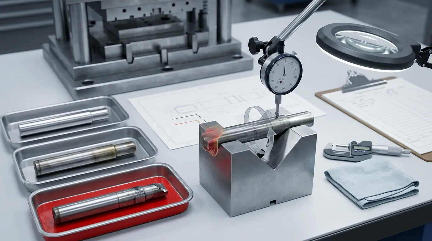
Routine QC should be based on risk and production history rather than one fixed interval for every punch.
Establish a baseline when the punch is first accepted, approved after setup, or returned from regrinding. Record dimensions and visible condition for the features most likely to change.
Trigger inspection when any of the following occurs:
- a planned production or maintenance interval is reached;
- the punch completes a high-risk or high-volume run;
- burr height or edge quality changes;
- stamped dimensions begin to drift;
- scratching or pickup appears on the part;
- stripping force increases;
- press load or operating sound changes;
- slug pulling or jamming occurs;
- a misfeed, collision, or material double-feed occurs;
- a nearby punch chips or breaks;
- the tool is removed for maintenance;
- lubrication, stock material, or process settings change;
- the punch returns from regrinding.
Compare current values with the baseline and approved service limits. Trend data can reveal gradual wear before a dimension crosses a rejection limit.
Production symptoms should be treated as inspection triggers, not automatic diagnoses. Burrs may result from a worn punch, but they can also reflect die wear, clearance, alignment, work-material variation, or stripper problems. The punching dies guide provides broader context on die materials, tolerances, clearance, and system-level tooling considerations.
Verify the Punch Again After Regrinding or an Abnormal Event
A sharp edge does not by itself prove that a reground punch is ready for service.
After regrinding, check:
- cutting-edge form;
- burr-free condition;
- overall length;
- working length or projection;
- tip diameter or profile;
- surface damage or overheating;
- remaining regrind allowance, where documented;
- identification and regrind history.
After a collision, misfeed, jam, or nearby breakage, also check:
- cracks;
- permanent bending;
- head or shoulder deformation;
- runout;
- seating surfaces;
- guide and retainer contact;
- the mating die opening and surrounding components.
Do not return a punch to service solely because no visible crack is present. A collision can change alignment or runout without producing an obvious surface defect.
Record the Result and Assign a Controlled Disposition
Inspection records should identify the punch, the requirement, the method, the result, and the final decision.
At minimum, record:
- part number;
- drawing number and revision;
- supplier;
- purchase order;
- lot or serial number;
- material and coating designation;
- inspection stage;
- characteristic inspected;
- specification and tolerance;
- measured result;
- instrument identification;
- inspector;
- inspection date;
- disposition;
- notes, photographs, or defect location where useful.
Use a controlled disposition rather than an informal “looks okay” decision.
| Finding | Possible disposition |
| All required characteristics conform | Accept or return to service |
| Result is inconsistent or close to a limit | Clean, stabilize, remeasure, or verify with a more capable method |
| Documentation is missing | Hold or quarantine until evidence is supplied |
| Repairable edge wear within an approved allowance | Send for engineering-approved regrinding |
| Crack, severe chipping, permanent bending, or unsafe head damage | Replace or reject |
| Dimension is outside the requirement | Quarantine and process as nonconforming |
| Same damage recurs repeatedly | Investigate clearance, alignment, guidance, retention, lubrication, and process conditions |
Nonconforming punches should be clearly identified and physically segregated so they cannot return to production accidentally.
SunshinePro states that its quality approach includes raw-material inspection, in-process monitoring, final testing, measuring equipment, and inspection reports. Buyers should still define the required inspection characteristics and documentation for each order rather than assume that one standard report fits every punch.
What to Request From a Punch Pin Supplier
A buyer should define inspection evidence before the order is released, especially for custom or critical punches.
Request the items that are relevant to the application:
- approved drawing and revision;
- part, lot, and serial identification requirements;
- drawing-specific inspection report;
- material certificate or certificate of conformity;
- heat-treatment or hardness evidence where specified;
- coating documentation where specified;
- approved deviations;
- packing and corrosion-protection requirements;
- identification of characteristics receiving 100% inspection;
- identification of characteristics inspected by sampling;
- measurement method for tight or complex tolerances;
- traceability between the punch, certificate, and inspection report.
Broad catalog statements are not a substitute for characteristic-level evidence. A supplier may state a general tolerance capability, but the buyer still needs confirmation that the required feature, material, geometry, and measurement method are suitable for the specific drawing.
SunshinePro lists tool steel, high-speed steel, carbide, CNC machining, precision grinding, EDM, vacuum heat treatment, and drawing-based customization on its punch-related pages. These published options can support an RFQ discussion, but the exact material, process, tolerance, coating, and inspection documentation should be confirmed for the individual part.
Punch Pin Inspection Checklist Summary
Use this condensed sequence for incoming, routine, post-regrind, and post-event inspections:
- Identify the inspection stage.
- Confirm the part number, lot or serial number, drawing, and revision.
- Review the purchase order, control plan, and document requirements.
- Inspect packaging and record transport damage.
- Clean the punch without damaging its edge or coating.
- Verify instrument condition, range, resolution, and calibration status.
- Inspect the cutting edge, tip, body, head, shoulder, radii, coating, and identification.
- Measure the dimensions and geometric characteristics required by the drawing.
- Use an instrument suitable for the feature and tolerance.
- Compare results with the approved acceptance source.
- Verify borderline results and account for measurement uncertainty.
- Record the specification, result, instrument, inspector, and date.
- Accept, hold, quarantine, regrind, replace, or reject through a controlled disposition.
- Investigate the wider die system when the same damage repeatedly returns.
For a custom or replacement punch, submit the approved drawing together with the required material, coating, inspection, and documentation needs. SunshinePro’s Die Punch Pin page provides its published product context, and the contact page can be used to request drawing review or clarify inspection-report requirements.
Share:


Written By Tonmoy
NEWS
GET SERVICE
With quality parts to meet every budget and friendly staff trained to make your visit informative and hassle free.
