



Punch Pins for Progressive Dies: Precision for High-Cycle Tooling
Punch pins for progressive dies must be selected as part of a complete station system, not as isolated hardened components. The operation performed at the station, strip material, feature geometry, cutting clearance, punch support, alignment, stripping conditions, and maintenance plan all affect punch reliability.
A harder material or premium coating cannot compensate for excessive unsupported length, poor alignment, incorrect clearance, or unstable strip feeding. For broader information about die types, materials, tolerances, and sourcing, see the punching dies guide (inferred). This guide focuses specifically on selecting, diagnosing, and specifying working punches for progressive tooling.
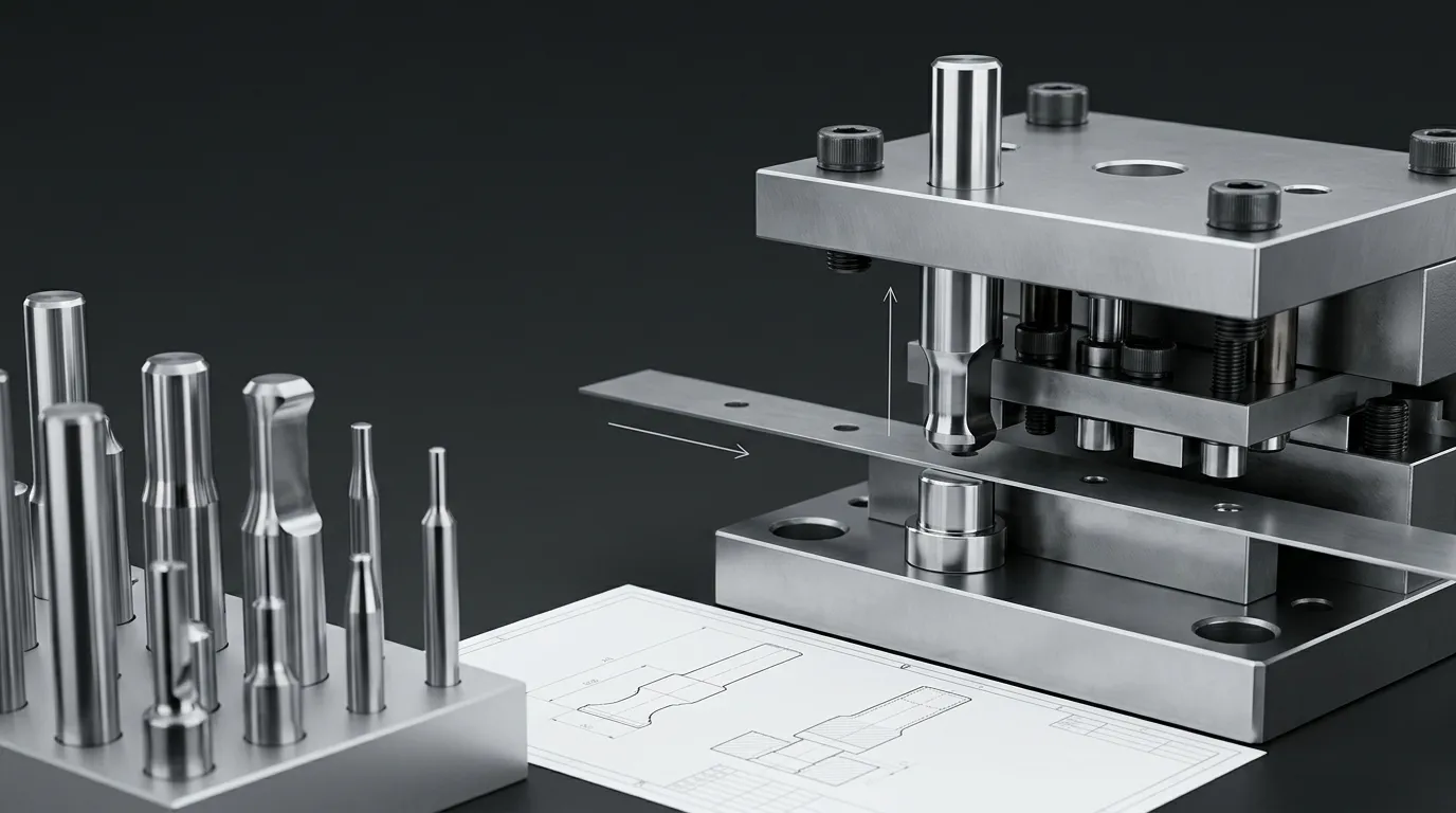
Why Progressive Dies Need Station-Specific Punch Specifications
A progressive die moves strip material through a sequence of stations. Each press stroke may pierce, notch, trim, form, or separate a feature while the feeder and pilots maintain the strip’s position.
This creates several demands that are less significant in a simple single-operation die:
- Errors at one station can affect every station that follows.
- Repeated side loading can gradually deflect a punch even before visible failure occurs.
- Feed or pilot errors can move the strip relative to the punch.
- Stripping force loads the punch during withdrawal from the stock.
- Slugs or loose material can interfere with later operations.
- Regrinding one punch can alter penetration or timing relative to other stations.
“High-cycle” therefore describes an operating condition, not a guaranteed number of strokes. Actual punch life depends on the complete combination of material, geometry, clearance, press conditions, lubrication, support, and maintenance.
Match the Punch to the Operation at Each Station
The first selection question should be: What does this punch do at its station?
Different operations create different loading patterns.
| Station operation | Main punch demand | Common risks to evaluate |
|---|---|---|
| Piercing | Repeated shearing through an enclosed profile | Edge wear, small-section breakage, slug pulling, burr growth |
| Notching or trimming | Shearing along a strip edge or partial contour | Asymmetric load, side deflection, uneven wear |
| Cutoff | Final separation of the part or carrier | High separation load, timing sensitivity, shock |
| Forming | Plastic deformation rather than simple shearing | Side thrust, material flow, galling, profile wear |
| Piloting | Strip registration rather than feature cutting | Position error, pilot entry damage, feed mismatch |
A small round piercing punch, for example, may be limited by slenderness and slug behavior. A long trimming profile may be more sensitive to uneven loading across its edge. A forming punch may need greater resistance to lateral force and material pickup.
Working Punches and Pilot Pins Perform Different Jobs
A working punch cuts or forms the strip. A pilot pin enters a previously produced hole or locating feature to refine strip position before critical operations occur.
The terms are sometimes mixed in supplier catalogues, so the drawing and RFQ should state the function clearly. The ISO 8695 punch terminology standard can help distinguish recognized punch types, while pilot design still needs to reflect strip thickness, feed conditions, and the actual locating method.
A pilot should not be selected using the same assumptions as a piercing punch. Its entry shape, location, clearance, and relationship with the feeder are central to its function.
Specify Geometry, Support, and Alignment as One System
Punch geometry cannot be evaluated only by nominal diameter or overall length. The designer must consider the smallest working section, profile transitions, shank, head, unsupported length, retention method, and mating die opening.
For a reliable specification, review:
- working-tip diameter or profile;
- smallest cross-section;
- unsupported length below the guide or holder;
- shank and head dimensions;
- transition radii where the part design allows them;
- straightness and relevant runout;
- concentricity between the working end and shank;
- profile tolerance for non-round punches;
- edge condition and regrind allowance;
- functional datums for replacement inspection.
A punch that is strong in compression can still fail if it is long, slender, poorly guided, or exposed to lateral load.
Profile and Unsupported Length Control Punch Stiffness
As unsupported punch length increases, resistance to deflection decreases. Narrow slots, small diameters, sharp profile changes, and asymmetric cutting edges further increase stress concentration.
Side loading is especially damaging because it can move the punch tip away from the intended axis. This changes the effective clearance around the profile. One side may then carry more cutting load, causing uneven wear or local chipping.
Technical guidance on improving punch life also connects lateral loading with punch-tip deflection and altered cutting clearance. This is why repeated breakage should not automatically lead to a harder punch material. The underlying problem may be geometry, support, feed position, or station loading.
The Holder, Backing Plate, Stripper, and Die Button Must Agree
The punch operates through a stack of supporting components:
| Component | Relationship with the punch | Problems if the relationship is poor |
| Punch holder or retainer | Locates and secures the shank | Position error, looseness, repeated misalignment |
| Backing plate | Supports the punch head under axial load | Head indentation, poor seating, local overload |
| Stripper plate | Removes stock and may guide the working end | High withdrawal load, tip movement, scoring |
| Die button or matrix | Receives the punch and establishes the cutting opening | Uneven clearance, edge damage, burr variation |
| Guide posts and bushings | Maintain upper-to-lower die alignment | Off-center entry, one-sided wear, chipping |
A guided stripper can help maintain the punch tip’s relationship with the die opening. MISUMI’s technical explanation of die structures notes the use of movable strippers for precision and progressive punching, including punch-tip guidance.
The wider roles of holders, backing plates, strippers, die buttons, and guide systems are covered in the die components guide. For this application, the important point is that changing only the punch may not solve a support or alignment problem.
Control Clearance, Strip Registration, and Slug Movement
The punch and die opening form a working pair. Their relationship affects cutting load, fracture behavior, burr formation, edge wear, and slug movement.
Clearance should be based on the actual:
- workpiece material;
- strip thickness;
- hardness or strength;
- feature geometry;
- required edge condition;
- punch and die material;
- alignment capability;
- expected wear behavior.
A nominal clearance value is not enough if the punch deflects or the die set is misaligned. The effective clearance may become larger on one side and smaller on the other.
Clearance Must Follow the Material and Feature
There is no single clearance percentage suitable for every progressive-die station.
Research on blanking has shown that clearance can influence punch wear, burr size, and the geometry of the cut feature. One peer-reviewed study on hardened steel sheet found measurable relationships among blanking clearance, punch wear, and burr development under its tested conditions.
The practical lesson is not to copy the study’s values into an unrelated die. Instead, use the material grade, thickness, strength, geometry, and quality requirement to establish a starting condition, then verify it through controlled inspection.
Uneven wear around the punch should trigger checks for:
- off-center punch entry;
- worn guide components;
- punch deflection;
- die-button movement;
- feeder or pilot error;
- uneven cutting load;
- local edge damage.
Registration and Slug Control Protect Downstream Stations
Progressive tooling depends on repeatable strip positioning.
A typical sequence is:
- The feeder advances the strip by the intended pitch.
- Pilots refine or confirm strip position.
- The stripper controls the stock near the working area.
- The punch enters the strip and die opening.
- The slug or trimmed material clears the station.
- The stripper removes the stock from the punch during return.
A feed or pilot problem can cause the punch to engage the strip off-center. Excessive stripping force can bend a slender punch or loosen its retention. A returned slug can remain on the punch face, re-enter the strip, or interfere with a later station.
Slug pulling therefore should not be treated only as a waste-removal issue. It can become a punch-damage and strip-progression problem.
Choose Material and Coating by the Dominant Failure Risk
Punch material should be selected after identifying the expected loading and failure mode. Maximum hardness alone is not a reliable selection method.
The main properties to balance are:
- wear resistance;
- toughness;
- compressive strength;
- resistance to plastic deformation;
- dimensional stability after heat treatment;
- resistance to chipping under shock or side load;
- suitability for the intended coating and finish.
Select the Substrate Before the Coating
| Application condition | Material direction to evaluate | Main limitation to check |
| Moderate wear with impact or variable loading | Tool steel or high-speed-steel category | May wear faster than a more wear-resistant option |
| Severe abrasive wear with stable alignment | Higher-wear tool steel, powder-metallurgy steel, or carbide | Cost, grinding, chipping, and support requirements |
| Small punch with repeated lateral load | Tougher steel and improved guidance | Wear may increase if the substrate is too soft |
| Stable, high-wear piercing condition | Carbide may be considered | Sensitive to shock, misalignment, and inadequate support |
| Adhesive wear or pickup | Suitable substrate plus finish, lubrication, or coating review | Coating cannot correct geometry or clearance errors |
Carbide can provide high wear resistance and compressive strength, but it is not automatically the best choice for every station. A carbide punch exposed to misalignment, shock, or side loading may chip where a tougher steel would tolerate the same disturbance.
SunshinePro lists SKH51, SKH9, DC53, ASP grades, and carbide among its punch-pin material categories. These are available directions, not proof that one grade is suitable for a specific die. The final choice requires the work material, geometry, support, production conditions, and failure history.
Use Coatings for a Defined Surface Problem
A coating should target a known surface issue such as abrasive wear, adhesive wear, galling, or material pickup.
Before selecting one, confirm:
- punch substrate and heat treatment;
- surface finish before coating;
- coating adhesion requirements;
- workpiece material and surface condition;
- lubrication;
- operating temperature;
- whether the punch will be reground;
- whether the coated surface includes the cutting edge, sidewall, or both.
SunshinePro lists TiN, TiCN, and DLC as custom punch-pin coating options. The appropriate choice depends on the substrate and contact conditions. No coating can correct an off-center punch, insufficient support, weak profile, or incorrect punch-to-die relationship.
Diagnose Wear and Breakage Before Replacing the Punch
The visible damage is not always the root cause. A symptom-based inspection reduces the risk of replacing the punch while leaving the system problem unchanged.
| Symptom | Possible variables | First checks |
| Burr increases gradually | Edge wear, die wear, clearance change | Inspect punch edge, die opening, feature quality trend |
| Wear appears mainly on one side | Deflection, misalignment, feed error, uneven clearance | Check guides, pilots, holder position, die-button alignment |
| Edge chips locally | Shock, excessive load, poor support, low toughness, tight local clearance | Inspect fracture location, punch support, die opening, load direction |
| Punch bends or buckles | Excessive unsupported length, small section, side load, overload | Check profile, guidance, station operation, strip position |
| Material adheres to the punch | Galling, poor lubrication, finish issue, unsuitable coating | Inspect pickup pattern, stock surface, lubrication, sidewall finish |
| Punch head fails | Poor seating, weak backing support, stress concentration, overload | Check holder, backing plate, head geometry, contact pattern |
| Slug follows the punch | Adhesion, vacuum effect, poor slug relief, punch-face condition | Inspect slug path, die relief, punch face, lubrication |
| Feature position drifts | Feed, pilot, guide, holder, or punch movement | Check strip pitch, pilot condition, holder fit, die alignment |
Repeated fracture deserves a broader investigation. The dedicated guide to punch breakage in stamping dies covers fracture causes and preventive actions in more depth.
A practical rule is to inspect the mating and supporting components whenever the same punch fails again. Replacing a damaged punch with an identical one will not correct a worn die button, loose holder, unstable feeder, damaged stripper, or misaligned guide system.
Plan Regrinding, Inspection, and Interchangeable Replacement
Regrinding restores the cutting edge, but it also removes punch length. That change can affect penetration, stripper interaction, station timing, and the relationship with other punches.
A maintenance plan should define:
- the condition that triggers sharpening;
- allowable stock removal;
- original and remaining punch length;
- edge geometry after grinding;
- required straightness or runout;
- whether coating must be reapplied;
- inspection of the mating die button;
- timing or penetration adjustment after installation;
- the minimum remaining serviceable length.
Do not wait for severe chipping if the punch is intended to be reground. Grinding away extensive damage removes more material and may make it harder to preserve the original profile.
Replacement punches also need functional datums. A drawing should identify which surfaces control:
- position in the holder;
- working-tip location;
- head seating;
- overall operating length;
- profile orientation;
- relationship with the mating die opening.
SunshinePro states that its quality approach includes incoming inspection, in-process monitoring, final testing, and inspection reporting. For an actual order, the buyer should still define which dimensions, datums, tolerances, and report fields must be verified.
Choose a Standard or Custom Punch Pin
A standard punch may be suitable when the required profile, dimensions, head style, retention method, material, and tolerances match an available design.
A custom punch is more likely to be required when the station uses:
- a non-round or proprietary profile;
- an unusual head or retention interface;
- a stepped or reduced working section;
- a special transition between shank and tip;
- an orientation feature;
- tight relationships between several datums;
- replacement dimensions tied to an existing die;
- a specific material, heat treatment, or coating combination.
| Selection question | Standard punch may fit | Custom punch may be needed |
| Is the working profile common? | Round or established catalogue profile | Special slot, contour, step, or asymmetric shape |
| Is the holder interface standard? | Common head and shank configuration | Proprietary retention or seating geometry |
| Are replacement datums simple? | Basic diameter and length control | Multiple positional, profile, or orientation controls |
| Is the material readily available in the required form? | Standard listed grade | Special grade, carbide form, or treatment requirement |
| Does the punch match an existing die? | Standard dimensions already used | Exact replacement compatibility required |
A worn sample can help identify the component, but it may not preserve the original dimensions. Wear, regrinding, bending, and edge damage can all distort the sample. A controlled drawing remains the preferred reference.
SunshinePro states that custom punch pins can be produced from drawings, samples, or specifications, with custom dimensions, shapes, head profiles, materials, and coatings. Its published processes include CNC machining, precision grinding, heat treatment, vacuum heat treatment, and EDM. Feasibility still needs to be confirmed for the specific geometry and tolerance combination.
Prepare the Drawing and RFQ Package
A complete inquiry helps the supplier evaluate material, manufacturing route, inspection, and replacement requirements without guessing.
Include:
- punch drawing and revision;
- station function: piercing, trimming, forming, cutoff, or piloting;
- strip material grade;
- strip thickness;
- workpiece hardness or strength where relevant;
- stock coating or surface condition;
- working profile and feature dimensions;
- mating die-button dimensions or intended clearance;
- shank, head, retention, and orientation details;
- functional datums;
- dimensional and geometric tolerances;
- required surface finish;
- edge condition;
- punch material and heat-treatment requirements;
- coating requirement, if already defined;
- unsupported length and guidance arrangement;
- press speed or production rate;
- expected production volume;
- lubrication condition;
- known failure symptoms;
- regrinding and spare-punch requirements;
- material certificate, heat-treatment record, coating record, or inspection-report requirements.
Published tolerance or hardness ranges should not be copied into the RFQ without checking whether they suit the drawing. SunshinePro’s punch pages publish capability ranges up to ±0.002 mm and HRC 58–68, but the achievable combination depends on punch size, profile, material, heat treatment, coating, and inspection method.
The most useful supplier question is not “How many cycles will this punch last?” without operating data. Ask the supplier to review the station conditions, identify manufacturing or inspection risks, and confirm the proposed material, geometry, and tolerance approach.
For a drawing-based feasibility review or quotation, submit the punch specification, strip information, station function, and known failure history through the SunshinePro contact page.
Share:


Written By Tonmoy
NEWS
GET SERVICE
With quality parts to meet every budget and friendly staff trained to make your visit informative and hassle free.
