



Tablet Break Line Design for Reliable Splitting and Tool Life
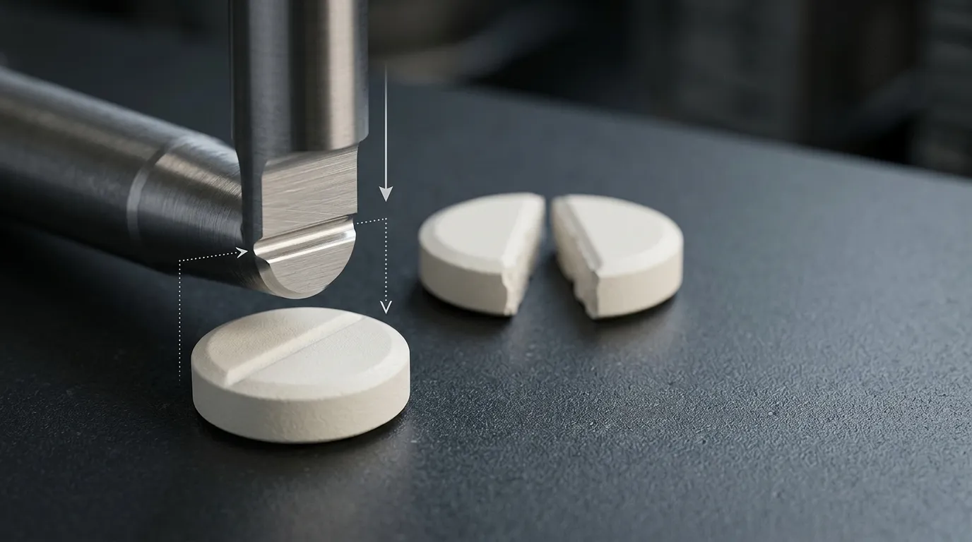
Tablet break line design is not a matter of making the deepest possible groove. A functional break line, also called a tablet score line, must guide the tablet along an intended fracture path while leaving enough strength for compression, ejection, coating, packaging, and handling.
The geometry must also be practical for the punch tip that forms it. A sharper or more protruding feature may help initiate a break, but it can increase local stress, reduce clearance between upper and lower punches, or make the tooling more vulnerable to chipping.
Break-line geometry is one specialized decision within the broader range of tablet press tooling types. The final design should be evaluated as a system involving the tablet shape, thickness, formulation, hardness range, punch configuration, press setup, and product-validation method.
What Makes a Tablet Break Line Functional?
A functional score line is intended to help a tablet divide into defined portions. Its performance cannot be judged only by how visible, straight, or symmetrical the groove appears.
A useful break line should support several outcomes:
- The tablet can be held and divided using the intended method.
- Fracture occurs close to the planned path.
- The resulting portions are reasonably consistent.
- Material loss from crumbs and fragments remains controlled.
- The intact tablet remains strong enough for production and handling.
- Subdivision does not create unacceptable changes in product performance.
The FDA guidance on tablet scoring treats scoring as a product-performance issue rather than a cosmetic feature. Depending on the product and market, evaluation may include splitting behavior, mass loss, friability, dissolution, stability, and performance across the proposed tablet-hardness range.
Functional Score Versus Decorative Groove
A tablet may contain a visible groove without being suitable for accurate subdivision. A decorative line may improve appearance or product recognition, but it should not be represented as a functional score unless the finished tablet has been tested for that purpose.
Visual inspection can confirm that the groove exists. It cannot prove that:
- The fragments have consistent mass.
- The active ingredient is evenly distributed.
- The tablet will divide similarly across the production hardness range.
- The split portions retain acceptable release characteristics.
- Patients or operators can reproduce the result using the intended method.
Tooling inspection and tablet-performance validation are therefore separate requirements.
Break-Line Geometry Variables and Their Trade-Offs
A score feature is defined by several connected dimensions. Changing one variable can affect the others, so break-line depth should never be specified in isolation.
| Design variable | Intended effect | Risk if taken too far | What must be verified |
|---|---|---|---|
| Depth or penetration | Reduces the tablet section that must fracture | Weak intact tablet, fragile center, tall punch feature | Tablet strength, split force, punch clearance |
| Groove width | Creates space for the score and affects its profile | Excess material removal or poor visual definition | Fracture behavior and manufacturability |
| Included angle | Concentrates the fracture path | Sharp punch geometry and higher local stress | Punch strength and subdivision consistency |
| Root radius | Controls the sharpness at the bottom of the score | Too small may weaken the tooling; too large may reduce fracture guidance | Tool stress and tablet breakability |
| Score length | Extends the guided fracture path | Edge chipping or interference with other features | Crack path and tablet-face layout |
| Position and orientation | Defines intended segment geometry | Unequal sections or misalignment | Symmetry, keying, and drawing orientation |
The correct combination depends on the tablet rather than on a universal score-line standard.
Depth, Width, and Remaining Tablet Section
A deeper groove leaves less tablet material beneath the score. This can reduce the force needed to start a fracture, but it can also weaken the tablet before the user intends to split it.
Depth must be considered relative to:
- Overall tablet thickness.
- Cup depth and face curvature.
- The location of the score across the curved surface.
- Tablet hardness.
- Whether the opposite face also contains a score.
- The height and shape of the punch-tip feature.
For example, the same nominal score depth may leave a substantial residual section in a thick, shallow-profile tablet but a much thinner section in a smaller tablet with a deep cup.
Groove width also affects the feature profile. It should provide a manufacturable transition without removing more material than necessary or creating a punch feature that is too thin to withstand repeated loading.
Angle and Root Radius
The included angle and root radius influence how strongly the score concentrates stress when the tablet is bent.
A sharp groove can encourage fracture to start at the intended line. The corresponding punch-tip feature, however, may contain a thin or sharp transition where mechanical stress becomes concentrated during each compression cycle.
A larger root radius generally creates a smoother tooling transition, but it may provide less concentrated fracture guidance in the tablet. This is why angle and radius should be reviewed together rather than treated as independent cosmetic dimensions.
Technical tablet-design sources such as the I Holland tablet-design paper discuss score penetration, radius, angle, punch stress, and the need to balance tablet breakability with robust tooling. These relationships are useful design principles, but they do not establish a universal dimension for every formulation.
Length, Position, and Interaction With Face Features
The score should follow the intended segment boundary and remain compatible with the tablet’s shape and face profile.
Its endpoints require particular attention. A line that extends too close to a tablet edge may create a vulnerable edge condition, while a line that stops too early may not guide the complete fracture path.
Other face features also affect placement:
- Logos and characters can interrupt a symmetrical fracture path.
- Deep embossing can compete with the score for available face area.
- Curved surfaces can change the effective score penetration along its length.
- Off-center placement can create unequal tablet sections.
- Multiple intersecting scores increase both tablet and punch-tip complexity.
The score, identification marks, and overall cup profile should be reviewed as one punch-face layout.
Why Tablet Properties Change the Result
Identical punch geometry can produce different subdivision behavior in different formulations.
Tablet size and shape influence how the product can be held and where bending forces are applied. A large oblong tablet may provide more leverage than a small round tablet, even when the score geometry appears similar.
Thickness and cup profile determine how much material remains under the groove. Formulation properties then control how that material responds to stress.
Relevant formulation behavior includes:
- Brittleness.
- Elastic recovery.
- Plastic deformation.
- Compactability.
- Internal bonding strength.
- Distribution of the active ingredient.
Compression force also changes the result because it influences tablet density and hardness. A score that performs well at one development condition may become difficult to break at a higher hardness or excessively fragile at a lower one.
The peer-reviewed review Tablet Scoring: Current Practice, Fundamentals, and Knowledge Gaps describes tablet subdivision as a multivariable problem involving patient use, tablet geometry, formulation, manufacturing conditions, and the selected test method.
The design should therefore be evaluated across the intended production range, not only on a single batch produced under ideal development conditions.
Single-Sided or Double-Sided Scoring?
A tablet can be scored on one face or on both opposing faces. Neither configuration is automatically better.
| Selection factor | Single-sided score | Double-sided score |
| Punch configuration | Score feature on one punch face | Coordinated features on upper and lower punches |
| Rotational alignment | Usually less demanding | Opposed features must remain aligned |
| Remaining tablet section | Controlled from one side | Reduced from both sides |
| Clearance risk | Lower for the unscored opposing face | Opposed protrusions can reduce punch-tip gap |
| Face-layout complexity | Leaves the opposite face available | Uses space on both faces |
| Setup sensitivity | Generally simpler | More dependent on keying and nominal lengths |
| Verification need | Product-specific | Product- and setup-specific |
A double-sided score may guide fracture from both surfaces, but it introduces additional mechanical and setup requirements. The two features must be positioned correctly relative to each other, and their combined penetration must not leave an excessively weak central section.
The choice should be based on the tablet geometry, formulation, intended segment pattern, available face area, tooling system, and validation results.
Alignment and Keying for Opposed Scores
Opposed score features must remain rotationally aligned during production. If one punch turns relative to the other, the score lines may no longer meet across the intended fracture plane.
Anti-turn keys and key guides can control punch orientation. Depending on the tooling arrangement, the lower punch may also require a keyed configuration.
The review should confirm:
- Which punch faces contain the score.
- The required angular orientation.
- The location of each key.
- Whether the press supports the intended keyed arrangement.
- How orientation will be checked during setup.
- Whether key or guide wear could allow movement over time.
This discussion is limited to score alignment. General upper- and lower-punch functions belong to the broader tooling system rather than this specific break-line decision.
Protecting the Punch Tip From Contact and Premature Failure
The score feature machined into a punch face may be narrow, sharp, or raised relative to the surrounding cup. These conditions can increase local mechanical stress.
Repeated compression subjects the punch to cyclic loading. A geometry with a thin section or abrupt transition may become more vulnerable to fatigue, while an overload, contact event, unsuitable material condition, or handling impact can contribute to chipping or brittle fracture.
A Pharmaceutical Technology discussion of tooling failures identifies fatigue, brittle fracture, punch design, material condition, and compaction load as relevant contributors to punch-tip damage.
The main tooling risks associated with a break line include:
| Risk | Possible cause | Possible consequence | Review action |
| Local stress concentration | Sharp angle, small radius, thin feature | Fatigue crack or chipped score feature | Review transitions and loading |
| Opposed feature contact | Insufficient upper/lower clearance | Immediate chipping or fracture | Check nominal lengths and tip gap |
| Rotational misalignment | Keying or setup problem | Uneven score, interference, poor fracture path | Verify orientation controls |
| Excess feature protrusion | Deep score geometry | Ejection interference or reduced clearance | Review feature height and tablet removal |
| Overload | High compression force or abnormal press condition | Plastic deformation or brittle failure | Confirm operating range |
| Marginal tablet design | Excessive penetration or weak central section | Premature tablet fracture | Test across production conditions |
Tool material and heat treatment affect durability, but they cannot compensate for direct punch contact, an unsafe stress concentration, or an incorrect press setup.
SunshinePro’s tablet press tooling page lists high-speed steel, CNC machining, heat treatment, dimensional inspection, and custom tooling from drawings or samples. These are relevant supplier capabilities, but they should not be interpreted as a guarantee of score performance or tool life for a specific product.
Upper-to-Lower Punch Clearance
Double-sided or highly protruding score features require careful clearance review.
The available gap depends on more than the visible tablet thickness. It can also be affected by:
- Feature height above each punch face.
- Upper and lower punch nominal lengths.
- Compression position.
- Press adjustment.
- Tool wear.
- Setup error.
- Deflection under load.
A practical review sequence is:
- Dimension the score features on both punch drawings.
- Confirm the nominal lengths of the upper and lower punches.
- Calculate the minimum expected separation at the operating position.
- Include a suitable safety margin for manufacturing and setup variation.
- Verify the arrangement during installation and trial compression.
- Inspect the punch tips after the trial for evidence of contact.
Press-specific values should come from the press manufacturer, approved tooling drawings, and project calculations rather than from a generic article.
Production and Handling Problems Linked to the Score
A scored tablet can survive compression but fail during a later production stage.
During ejection, the lower punch raises the tablet through the die. A weak score area may chip as the tablet moves, while a protruding punch feature may complicate release from the punch face.
Take-off introduces another contact event. If the tablet has already been weakened excessively, lateral movement can cause edge damage or premature fracture.
Coating and packaging can also expose a marginal design:
- Coating may bridge across the groove.
- Coating film may crack when the tablet is divided.
- Tablets may rub against each other during coating and handling.
- Packaging equipment may apply local loads.
- Transport vibration may break tablets that lack sufficient intact strength.
These problems do not prove that the score is always the root cause. The formulation, ejection force, tooling condition, coating process, packaging design, and handling system may also contribute.
The purpose of the break-line review is to determine whether the score has created an avoidable weak section or tooling feature before wider process changes are made.
Diagnose the Failure Before Changing the Break Line
A score redesign should follow evidence, not assumptions.
| Observed problem | Possible causes | Evidence to collect |
| Tablet is difficult to divide | Shallow score, high hardness, unsuitable formulation, poor grip, unsuitable test method | Hardness data, breaking method, segment results |
| Tablet breaks away from the score | Misplaced line, formulation fracture pattern, asymmetric geometry | Fracture location, cross-section, tablet dimensions |
| Unequal fragments | Off-center score, rotational misalignment, inconsistent splitting method | Tool orientation, segment mass, user method |
| Tablet chips during ejection | Weak edge, excessive penetration, high ejection force, tooling condition | Ejection data, chip location, punch and die inspection |
| Tablet separates into a cap | Air entrapment, formulation or compression issue, tooling configuration | Defect plane, press parameters, formulation review |
| Punch score feature chips | Direct contact, stress concentration, overload, handling damage | Tip-gap check, fracture surface, setup records |
Capping should not be treated as another name for a score-related break. A score is intended to guide fracture through a defined plane, while capping usually involves separation of the top or bottom portion of the tablet from the main body.
Where the defect pattern indicates cap separation rather than failure along the intended score, the reader should move to the dedicated tablet capping tooling solutions guidance instead of expanding the break-line article into a full capping investigation.
How to Validate a Functional Break-Line Design
A functional break line requires verification at several levels. Dimensional inspection alone is not enough.
1. Inspect the Tooling
Confirm that the manufactured punches match the approved drawings.
Relevant checks may include:
- Score depth.
- Width.
- Included angle.
- Root radius.
- Length and endpoint position.
- Orientation.
- Key position.
- Upper and lower punch nominal lengths.
- Surface condition.
- Opposed-feature clearance.
SunshinePro describes dimensional inspection and inspection reporting within its quality-control practices. These checks can verify whether the tool conforms to the specification, but they do not establish how a pharmaceutical formulation will behave.
2. Conduct Representative Press Trials
Trials should use the intended formulation and a relevant operating window.
The trial plan should consider:
- Low and high tablet-hardness conditions.
- Expected compression-force range.
- Production speed where it affects performance.
- Ejection and take-off behavior.
- Tool orientation.
- Evidence of upper/lower punch contact.
- Tablet chipping or premature fracture.
- Repeated-cycle effects on the punch feature.
A single successful compression event does not prove that the design is robust for production.
3. Evaluate the Whole Tablet
Before subdivision, confirm that the scored tablet remains suitable for handling.
Evaluation may include:
- Visual integrity.
- Breaking force or hardness.
- Friability.
- Resistance to coating and packaging damage.
- Stability during normal storage and transport.
- Consistency across batches and operating conditions.
The score should not make the intact tablet so weak that it breaks before the intended use.
4. Evaluate the Split Portions
Subdivision testing should represent the intended method, such as hand splitting or a defined mechanical device.
Depending on the product and regulatory strategy, review:
- Ease of splitting.
- Fracture location.
- Segment mass variation.
- Material loss.
- Content uniformity.
- Friability of the resulting portions.
- Dissolution or release behavior.
- Stability of split portions where required.
Equal mass does not automatically prove equal active content. If the formulation contains an uneven distribution of active ingredient, two fragments with similar weight may still differ in drug content.
The FDA guidance is relevant to products intended for the United States. Worldwide projects must confirm requirements in each applicable market, particularly for modified-release products or dosage forms where subdivision may alter release behavior.
Tooling Inspection Is Not Product Validation
The responsibility boundary should remain clear:
| Activity | What it confirms | What it does not confirm |
| Drawing approval | Intended dimensions and configuration | Finished tablet performance |
| Tooling inspection | Conformance to the drawing | Reliable subdivision |
| Press trial | Compression and handling behavior under trial conditions | Full commercial-batch consistency |
| Pharmaceutical testing | Product and segment performance | Long-term tooling life under every press condition |
A tooling supplier can manufacture and inspect a punch feature. The pharmaceutical manufacturer or product owner must validate the final tablet.
Information to Prepare Before Ordering Scored Tablet Tooling
A complete enquiry reduces the risk of designing the score without enough product or press information.
Tablet Data
Provide:
- Tablet shape.
- Diameter or major and minor dimensions.
- Overall thickness.
- Cup profile.
- Target number of portions.
- Required segment symmetry.
- Coating status.
- Logos, characters, or other face features.
- Intended hand or mechanical splitting method.
Break-Line Data
Define, where already established:
- Single- or double-sided configuration.
- Depth.
- Width.
- Included angle.
- Root radius.
- Length.
- Endpoint position.
- Orientation.
- Relationship to logos or embossing.
Where the dimensions remain under development, identify them as proposed rather than validated.
Formulation and Process Data
Include relevant information such as:
- Development status of the formulation.
- Intended hardness range.
- Expected compression-force range.
- Known brittleness or elastic-recovery concerns.
- Ejection or take-off issues from prior trials.
- Coating, packaging, and handling requirements.
A tooling supplier does not need the full confidential formulation to understand that the tablet’s fracture behavior and hardness range affect the score design. The level of disclosure can be agreed within the project.
Press and Tooling Data
Confirm:
- Press model.
- Tooling standard.
- Punch type.
- Upper and lower punch nominal lengths.
- Keying requirements.
- Key orientation.
- Available lower-punch keying.
- Existing tooling drawings or samples.
- Inspection-document requirements.
SunshinePro states that it supplies custom tablet press tooling from drawings or samples and lists size customization, material-selection support, CNC machining, heat treatment, and dimensional inspection. Final material, geometry, inspection scope, and project suitability should still be confirmed for the specific enquiry.
Final Design Review Principles
Before approving a scored-tablet tooling drawing, confirm five points:
- The score geometry has been reviewed relative to the tablet thickness, cup profile, formulation, and hardness range.
- The selected single- or double-sided configuration matches the intended fracture path.
- Opposed features have adequate alignment and upper/lower punch clearance.
- Compression, ejection, take-off, coating, packaging, and handling risks have been considered.
- The validation plan separates tooling conformance from whole- and split-tablet performance.
There is no universal break-line geometry that guarantees accurate splitting and long tool life. The most reliable approach is to combine a complete tablet specification, a controlled punch-face design, suitable press setup, and product-specific validation.
For a custom tooling enquiry, prepare the tablet drawing, score dimensions, press details, keying requirements, and requested inspection records before contacting SunshinePro.
Share:


Written By Tonmoy
NEWS
GET SERVICE
With quality parts to meet every budget and friendly staff trained to make your visit informative and hassle free.
