


Mold Limit Pin Material Selection for Impact and Wear
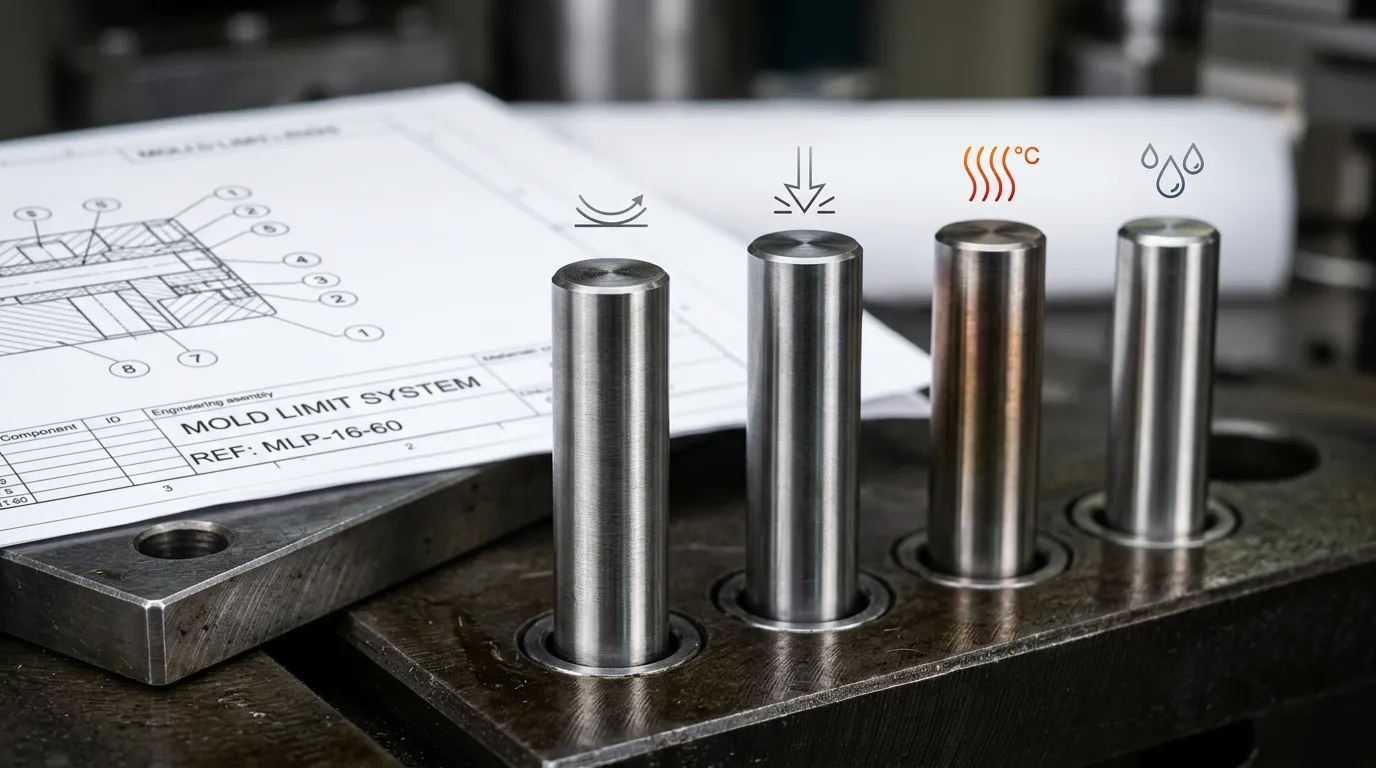
Mold limit pin material selection should start with the pin’s actual loading conditions, not with the highest available hardness. A material that resists surface wear may still chip under repeated impact, while a tough material may deform if its finished hardness is too low.
Limit pins belong to the wider category of mold standard parts (inferred), but their material requirements depend on a narrow set of factors: impact severity, contact wear, operating temperature, corrosion exposure, pin geometry, and the condition of the mating plate.
For controlled service, a medium-carbon steel such as S45C may be suitable when its heat-treated condition matches the application. Repeated severe impact may justify a shock-resistant tool steel. High temperatures or corrosive conditions can require a different material family. There is no single best material for every mold limit pin.
Choose the Material by Service Condition, Not Hardness Alone
The first step is to identify the condition most likely to damage the pin. A pin exposed to abrupt stopping loads needs a different property balance from one experiencing gradual contact wear.
Quick Material-Selection Matrix
| Service condition | Main risk | Property to prioritize | Material category to evaluate | Main limitation or verification point |
|---|---|---|---|---|
| Controlled impact and moderate wear | Gradual indentation or wear | Adequate hardness with reasonable toughness | Medium-carbon steel such as S45C | Confirm the finished hardness, support, contact area, and expected cycle demand |
| Repeated abrupt impact | Chipping, cracking, or impact fracture | Toughness and shock resistance | S7-type shock-resistant tool steel | Higher hardness alone may reduce impact tolerance |
| High contact wear with limited shock | Dimensional loss at the contact face | Wear resistance and compressive strength | Wear-oriented tool steel | Verify that toughness remains sufficient for the actual impact level |
| Elevated operating temperature | Softening, thermal fatigue, or dimensional change | Hot strength and thermal stability | H13-type hot-work tool steel | Usually unnecessary for normal-temperature service |
| Humid or corrosive environment | Rust, pitting, or surface deterioration | Corrosion resistance | Stainless mold or tool steel | Confirm that its hardness and toughness also meet the load |
| Mixed or unclear failure conditions | Repeated unexplained damage | Balanced properties and root-cause review | Application-specific engineering review | Do not change material before checking alignment, geometry, and mating surfaces |
This matrix narrows the options, but it does not replace a drawing and application review. Diameter, unsupported length, contact-face geometry, side loading, and heat treatment can change how the same steel performs.
Confirm That the Component Is a Limit Pin Before Selecting Its Material
The term “mold limit pin” is not used consistently across every supplier, catalog, or drawing. It may also appear as a mold stop pin, ejector-plate limit pin, or, in some assemblies, a stop disk.
A typical stop or limit pin restricts the movement of an ejector plate or another mold mechanism. Some stop-pin designs are installed between an ejector plate and a rear clamping plate to control the plate’s resting position and prevent uncontrolled metal-to-metal contact. Other drawings may use a limit pin in a slider mechanism.
The drawing should confirm the function before any material is selected.
| Component | Primary function | Typical material concern |
| Limit or stop pin | Restricts mechanism or ejector-plate travel | Impact, contact wear, deformation, and fracture |
| Guide pin | Aligns moving and stationary mold halves | Sliding wear, straightness, fit, and lubrication |
| Ejector pin | Pushes the molded part from the cavity | Sliding wear, bending, temperature, and surface finish |
| Return pin | Returns or positions the ejection system | Repeated movement, alignment, and compressive loading |
| Dowel pin | Locates two components accurately | Shear strength, fit, and positional accuracy |
Guide pins and bushings belong to a different alignment system. Their fit, clearance, and lubrication requirements are covered separately in the guide to mold pins and bushings.
Balance Hardness, Toughness, Impact Resistance, and Wear Resistance
Four properties control most limit-pin material decisions.
Hardness helps the contact face resist indentation and some forms of wear. If the surface is too soft for the applied load, the end of the pin can lose its shape or effective height.
Toughness is the ability to resist cracking and absorb energy before fracture. It becomes critical when the pin receives abrupt, repeated contact rather than a gradual compressive load.
Impact resistance describes how well the material handles sudden loading. It is affected by toughness, hardness, heat treatment, geometry, and defects such as sharp transitions.
Wear resistance helps the pin maintain its dimensions under repeated contact. It depends on more than hardness. Steel composition, carbide structure, surface condition, contact pressure, contamination, and relative movement all affect wear.
A harder steel is not automatically a better limit-pin material. High hardness can reduce plastic deformation, but if the steel lacks sufficient toughness, the failure may change from mushrooming to chipping or cracking.
The material therefore needs enough hardness to retain the contact face and enough toughness to survive the way the load is applied. Technical guidance from Uddeholm on tool-steel heat treatment also shows that final properties depend on alloy design, microstructure, hardening, and tempering rather than the grade name alone.
What Happens When the Pin Is Too Soft?
Possible symptoms include:
- Indentation at the contact face
- Mushrooming around the impacted end
- Accelerated dimensional wear
- Reduced effective stop height
- Changes in ejector or mechanism travel
- Surface damage on both the pin and mating plate
These symptoms do not always mean the material grade is wrong. Excessive contact stress, a small contact area, off-axis loading, inadequate support, or an incorrect heat-treated condition can produce similar damage.
What Happens When the Pin Is Too Hard or Insufficiently Tough?
An overly brittle pin may develop:
- Small edge chips
- Cracks near the contact face
- Sudden fracture
- Damage at diameter transitions
- Failure under slight side loading or misalignment
Increasing hardness without checking toughness can also move the damage elsewhere. The pin may remain intact while the mating plate begins to indent or crack.
Compare Material Categories for Mold Limit Pins
A buying decision should compare material families by their property balance and best-fit conditions. The grades below are engineering reference categories. Except for S45C, they should not be treated as confirmed SunshinePro material offerings without direct confirmation.
| Material category | Main strengths | Best-fit condition | Main trade-off |
| S45C/45# medium-carbon steel | Practical machinability, established availability, heat-treatment flexibility | Controlled impact and moderate wear | May be insufficient for severe shock, heat, or corrosion without an appropriate finished condition |
| S7-type shock-resistant steel | High toughness, impact resistance, and balanced wear performance | Repeated abrupt impact or chipping history | Requires controlled heat treatment and may increase cost |
| H13-type hot-work steel | Hot strength, toughness, and thermal stability | Elevated temperature or repeated thermal cycling | Unnecessary for many normal-temperature applications |
| Wear-oriented tool steel | Strong wear resistance and dimensional retention | High contact wear with limited impact | Higher wear resistance may come with reduced impact tolerance |
| Stainless mold/tool steel | Corrosion resistance with mold-grade mechanical properties | Humidity, corrosive cleaning, storage, or process exposure | Material choice must still satisfy impact and hardness requirements |
S45C/45# Steel for Standard or Controlled Service
SunshinePro’s current Mold Limit Pin product page publishes S45C, also described as 45# steel, as the product material.
S45C is a medium-carbon steel designation. It may be a practical option when:
- The stopping load is controlled
- Impact is not unusually severe
- Wear demand is moderate
- The pin has adequate diameter and support
- The contact face is properly aligned
- The final heat-treated condition is verified
- Replacement and maintenance requirements are predictable
The material name alone does not establish performance. The buyer still needs to confirm the final hardness, heat-treatment condition, test method, geometry, and loading environment.
International buyers may also encounter SAE 1045 in cross-reference tables. Nippon Steel lists S45C and SAE 1045 together in its special-steel grade documentation, but apparent equivalents should not be substituted automatically. The governing standard, chemical composition, delivery condition, and required properties must be checked.
S7-Type Shock-Resistant Steel for Repeated Impact
An S7-type tool steel is relevant when the pin repeatedly receives abrupt impact or when the current pin shows chipping and cracking rather than gradual wear.
Shock-resistant steel is selected for a different reason from a high-wear steel. Its main advantage is the ability to combine useful hardness with stronger resistance to impact fracture. Uddeholm’s documentation for its AISI S7-type Compax Supreme steel highlights toughness, impact resistance, wear resistance, through-hardening capability, and dimensional stability.
This category may be worth evaluating when:
- The stopping event is sudden
- Cycle frequency is high
- Small chips appear at the contact face
- The pin experiences occasional side loading
- A harder wear-focused steel has fractured prematurely
The trade-offs can include more demanding heat treatment, higher material cost, and different machinability.
H13-Type Hot-Work Steel for Elevated Temperature
H13-type hot-work tool steel is relevant when the pin operates at a temperature high enough to affect normal steel hardness, strength, or dimensional stability.
Possible use conditions include:
- High mold operating temperatures
- Repeated heating and cooling cycles
- Significant heat transfer from nearby mold regions
- Service in which hot strength matters as much as room-temperature hardness
Uddeholm’s H13 technical overview describes the category in terms of toughness, elevated-temperature resistance, wear resistance, and thermal stability.
H13 should not be treated as an automatic upgrade. For a normally cooled mold with moderate impact, its thermal properties may provide little practical advantage.
Stainless or Wear-Oriented Steel for Special Conditions
Stainless mold steel should be considered when corrosion is a real service risk rather than a theoretical concern. Relevant conditions may include humid storage, condensation, corrosive cleaning agents, or a production environment that repeatedly exposes the pin to moisture.
A stainless mold steel such as the category represented by Uddeholm Stavax ESR can combine corrosion resistance with useful wear and hardening characteristics. The final selection still needs to satisfy the impact load.
Wear-oriented tool steel belongs to a different category. It may help where repeated contact gradually removes material but impact remains controlled. A high-wear steel should not be chosen solely because the current pin is wearing. If the contact is also abrupt, insufficient toughness can create a more serious fracture risk.
Specify the Heat-Treated Condition, Not Only the Steel Grade
Two pins made from the same nominal steel can perform differently if their heat treatments are different.
The final condition depends on factors such as:
- Hardening method
- Quenching conditions
- Tempering
- Section size
- Surface decarburization control
- Core condition
- Distortion control
- Final grinding or finishing
Through-hardening develops properties through the pin section. Surface-hardening processes modify the outer layer while leaving a different core condition. Neither approach is automatically superior; suitability depends on the required contact hardness and core toughness.
A purchase specification should state more than “hardened steel.” It may need to define:
- Material designation and governing standard
- Required heat-treated condition
- Hardness scale
- Acceptable hardness range
- Test location
- Surface or core requirement
- Dimensional requirements after heat treatment
- Required inspection documentation
Rockwell hardness testing should follow an appropriate recognized method. ISO 6508-1:2023 specifies regular and superficial Rockwell hardness test methods for metallic materials.
SunshinePro’s product page currently lists both vacuum heat treatment and a hardness of 15–17 HRC. Buyers should request confirmation of how those statements apply to the ordered pin, including the final material condition and hardness-test location. The published value should not be treated as a universal recommendation for all limit-pin applications.
Why Coatings or Surface Treatments Cannot Correct the Wrong Substrate
A surface treatment may improve wear behavior or alter friction, but it cannot give an unsuitable core the toughness needed to survive severe impact.
The complete system includes:
- Base steel
- Core heat-treated condition
- Surface treatment
- Contact geometry
- Pin support
- Mating material
- Load direction
A hard surface over a weak or brittle substrate may still crack, bend, or fail below the treated layer.
Use Failure Symptoms to Identify the Property That Is Missing
Before changing steel grades, inspect how the current pin failed.
| Failure symptom | Possible material-related issue | Other conditions to inspect |
| Indentation | Insufficient hardness or compressive strength | Small contact area, excessive load, soft mating surface |
| Mushrooming | Excessive plastic deformation | Off-axis impact, unsupported end, poor contact geometry |
| Rapid surface wear | Inadequate wear resistance or surface condition | Contamination, fretting, misalignment, rough mating surface |
| Chipping | Insufficient toughness or excessive brittleness | Sharp edges, impact concentration, heat-treatment defects |
| Cracking or sudden fracture | Poor toughness or unsuitable finished hardness | Side loading, diameter transition, internal defect, misalignment |
| Bending | Insufficient section strength | Excessive unsupported length, off-axis force, poor support |
| Corrosion or pitting | Inadequate corrosion resistance | Moisture, cleaning chemicals, storage conditions |
These symptoms identify areas to investigate, not definitive causes. A pin that bends may need a tougher material, but it may also need a larger diameter, shorter unsupported length, or improved alignment.
Check the Mating Plate Before Increasing Pin Hardness
The pin and mating plate form one contact system. Changing only the pin can transfer damage to the other component.
Before increasing hardness, check:
- Mating-plate material and hardness
- Contact-face flatness
- Contact area
- Load alignment
- Plate support
- Existing indentation or cracking
- Surface contamination
The goal is not to make the replaceable pin as hard as possible. The goal is to control wear and deformation across the assembly without creating a brittle failure point.
Provide the Supplier with the Conditions That Control Material Selection
A supplier cannot make a reliable recommendation from diameter and length alone. The inquiry should include the information that controls loading and failure.
Provide:
- The pin’s exact function
- Installation location
- Current drawing and revision
- Diameter and overall length
- Unsupported length
- Contact-face geometry
- Mechanism or ejector force, where known
- Cycle frequency
- Expected service duration
- Normal and peak operating temperature
- Moisture or chemical exposure
- Mating-component material and hardness
- Current pin material
- Existing heat-treatment specification
- Photographs or descriptions of previous failures
- Required material and inspection documents
SunshinePro states that standard and non-standard sizes are available and that non-standard mold parts can be processed from drawings. Its product page also states that material-selection advice is available. These points support a drawing-based review, but they do not confirm that every material category discussed in this guide is available.
Verify the Material and Finished Condition Before Approving the Order
A material recommendation is only useful if the delivered parts can be checked against it.
Before approval, confirm:
- Exact material designation
The purchase order should identify the grade and governing standard rather than relying on a broad label such as “tool steel.” - Material certificate or test report
Where required, the document should identify the material batch or heat and provide traceable grade information. - Heat-treatment condition
Confirm whether the pin is supplied annealed, normalized, quenched and tempered, through-hardened, or surface treated. - Finished hardness
State the test scale, required range, and test location. A surface reading may not describe the core condition. - Dimensional inspection after heat treatment
Heat treatment can influence straightness, diameter, length, and contact-face geometry. - Surface-treatment documentation
When a coating or treatment is specified, confirm that it applies to the ordered material and finished condition. - Batch traceability
The delivered parts should be connectable to the relevant material and inspection records.
SunshinePro’s guide to precision mold parts provides broader context on material, tolerance, finish, traceability, and supplier quality control. The limit-pin order should still define which records are actually required; buyers should not assume that every standard order includes every type of certificate.
Supplier Claims That Need More Evidence
Treat the following statements as incomplete unless the supplier provides supporting details:
- “The highest hardness will last longest.”
- “This tool steel is suitable for every mold.”
- “These grades are equivalent,” without naming the governing standards.
- “Vacuum heat treated,” without stating the final condition or hardness.
- “High wear resistance,” without defining the contact condition.
- “High impact resistance,” without identifying the grade and heat treatment.
- “Certified material,” without a certificate tied to the delivered batch.
- “Longer service life,” without comparable operating conditions.
ASTM A681-24 reinforces the broader principle that tool-steel selection depends on design, service conditions, and the properties required by the application.
Evaluate SunshinePro’s Published S45C Option Against the Application
SunshinePro’s current Mold Limit Pin page publishes:
- S45C/45# steel
- 15–17 HRC
- Standard and non-standard sizes
- Material-selection support
- Vacuum heat treatment
This information provides a commercial baseline, but suitability still depends on the application.
The published S45C option may be evaluated first where impact is controlled, wear is moderate, temperature is not unusually high, and corrosion is not a major concern.
A custom material or processing review becomes more important when:
- Pins repeatedly chip or crack
- The contact face mushrooms
- Bending occurs
- The mold runs at elevated temperature
- Corrosion is present
- The mating plate is being damaged
- A specific core or surface hardness is required
- The current material has failed despite correct installation
Alternative steel categories discussed in this guide should not be assumed to be available from SunshinePro. Their availability, heat treatment, documentation, and dimensional feasibility need direct confirmation.
Select the Pin as Part of the Contact System
A defensible mold limit pin material selection follows six checks:
- Confirm the component’s exact function.
- Identify whether impact, wear, heat, corrosion, or bending is the dominant risk.
- Select the required balance of hardness and toughness.
- Specify the material’s finished heat-treated condition.
- Check the mating plate, contact face, support, and alignment.
- Verify the material, hardness, dimensions, and traceability before approval.
For an application that falls outside the published S45C baseline, submit the limit-pin drawing and service conditions for review. Include the cycle demand, operating temperature, environment, mating material, and any existing failure symptoms so the material and finished condition can be evaluated together.
Share:


Written By Tonmoy
NEWS
GET SERVICE
With quality parts to meet every budget and friendly staff trained to make your visit informative and hassle free.
