



Mold Positioning Pin Misalignment: Symptoms and Troubleshooting
Mold positioning pin misalignment can cause binding during closure, uneven contact, parting-line mismatch, flash, abnormal wear, or inconsistent part dimensions. The pin itself may be damaged, but it is only one possible cause. A worn bushing, loose mounting bore, contaminated parting surface, damaged interlock, thermal growth, poor mold installation, or machine-platen condition can create similar symptoms.
The correct approach is to identify when the problem occurs, inspect the entire mating system, measure the suspected geometry, and repair only the verified cause. For broader information about component fit, wear, materials, and lubrication, see SunshinePro’s guide to mold pins and bushings (inferred).
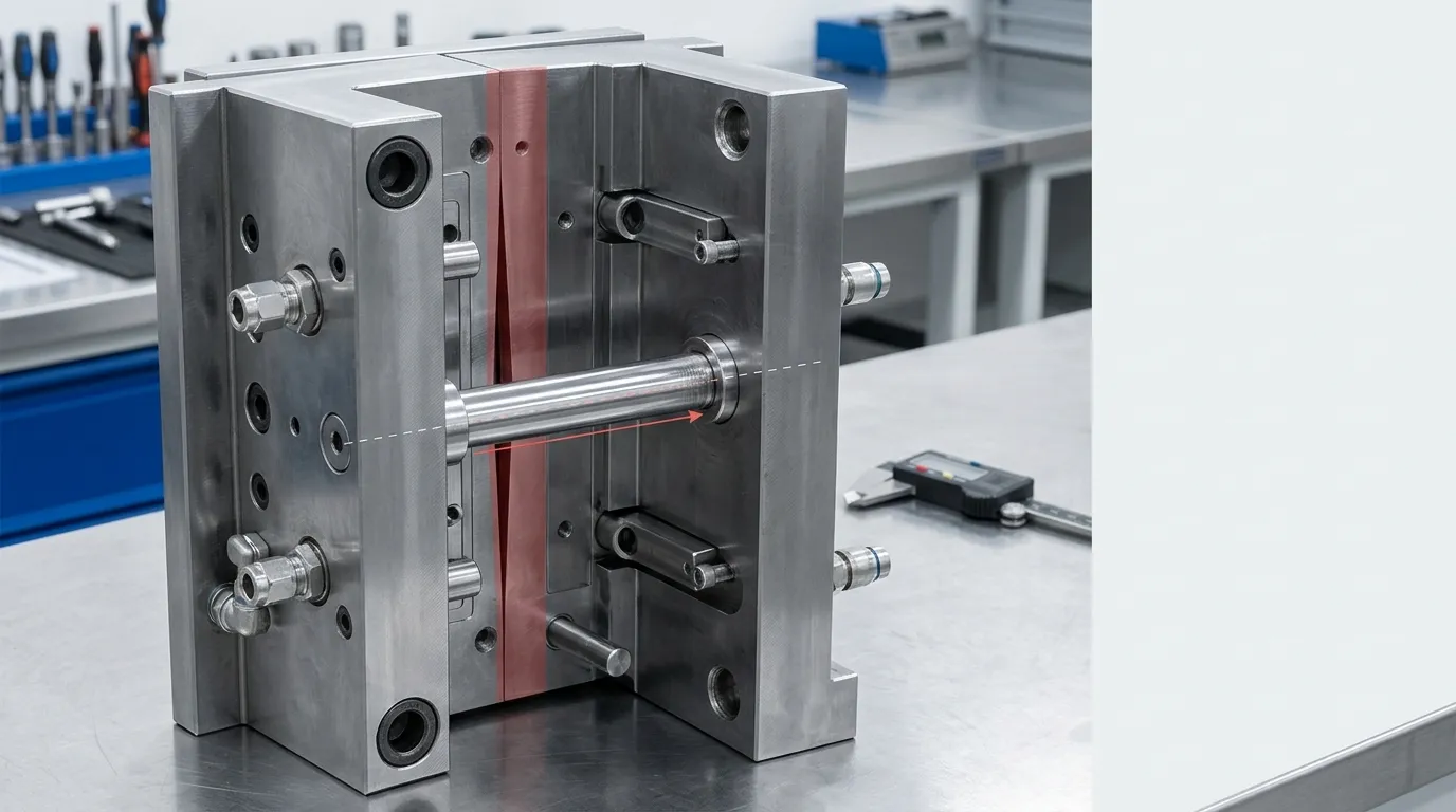
First Confirm What the “Positioning Pin” Does in This Mold
“Positioning pin” is not used consistently across every mold design. Before troubleshooting, identify the component by function rather than relying only on its name.
| Component | Main role | Diagnostic implication |
|---|---|---|
| Locating or dowel pin | Establishes repeatable position between components or plates | Check its geometry, mounting fit, orientation, and mating hole or bushing |
| Guide pin, leader pin, or guide pillar | Guides the mold halves during engagement | Check straightness, wear, bushing clearance, and side-loading marks |
| Guide or locating bushing | Receives the pin and controls the mating interface | Check bore wear, ovality, position, retention, and entry damage |
| Side interlock or taper lock | Helps establish or maintain final mold registration | Check contact pattern, wear, damage, and engagement |
| Shutoff or precision mating surface | Contributes to final alignment and sealing | Check for impact marks, mismatch, local gaps, and edge damage |
A guide pin may control the initial closure path while another locating feature controls final core-to-cavity registration. Replacing the guide pin will not solve the problem if the final interlock, bushing, mounting bore, or mold plate is out of position.
SunshinePro’s separate guide to mold guide pins covers broader guide-pin function, wear, and selection. Here, the focus is determining why an installed mold is no longer aligning correctly.
Symptoms That Point to a Mold-Registration Problem
The timing and location of a symptom often provide more useful evidence than the symptom alone.
| Symptom | When it appears | Possible subsystem | First confirming check |
| Binding at the same point during closing | Cold or no-load closure | Bent pin, skewed bushing, damaged interlock, burr, or plate-position error | Stop at the first contact point and inspect for one-sided witness marks |
| Scraping, vibration, or impact noise | During pin or interlock engagement | Side loading, insufficient clearance, contamination, or damaged entry geometry | Inspect the pin, bushing mouth, interlocks, and nearby surfaces |
| Abnormal heat near the guide system | After repeated cycling | Friction, poor lubrication, tight fit, side loading, or galling | Check for scoring, discoloration, lubricant condition, and uneven contact |
| Mold does not close squarely | Setup or controlled closing | Mounting error, obstruction, plate distortion, machine-side alignment, or damaged positioning components | Inspect mounting, locating features, parting surfaces, and plate relationships |
| Parting-line step or mismatch | During production | Registration loss, plate movement, interlock wear, or machine-side loading | Compare the mismatch location with contact and wear patterns |
| Localized flash | Under injection pressure | Misregistration, damaged shutoff, insufficient clamping, contamination, or process conditions | Check whether the mold aligns without pressure and inspect the affected shutoff |
| Dimensional variation between cycles | After warm-up or under load | Changing clearance, thermal growth, plate movement, or worn positioning features | Compare cold, warm, and production-condition measurements |
| One-sided pin or bushing polishing | Progressive over time | Mispositioned bore, bent pin, plate error, or uneven machine loading | Measure pin runout and inspect bore position and perpendicularity |
DME’s technical guidance on mold interlocks identifies flash, dimensional problems, and component damage as possible consequences of improper mold alignment. It also notes that worn leader pins and bushings, thermal variation, mold weight, and equipment condition can affect registration. See DME’s mold-alignment technical guidance.
Flash alone does not prove positioning pin failure. Flash can also result from damaged shutoffs, trapped material, insufficient clamping, excessive pressure, or other tooling and process conditions. Treat it as evidence that requires further inspection.
Symptoms During Mold Closing
Closure-related symptoms usually point toward the engagement path.
Look for:
- Resistance that begins at the same position during each closing attempt.
- A pin entering the bushing off-center.
- Fresh contact marks on only one side of the pin.
- Scraping at the bushing entrance.
- Impact marks on interlocks or shutoffs.
- A visible gap on one side of the parting line.
- A pin, bushing, or retainer moving in its mounting feature.
A repeatable hard-contact point is more likely to involve geometry, obstruction, or mounting position than a process-setting problem.
Symptoms on the Molded Part or Parting Surface
Production evidence may include:
- A step across the parting line.
- Flash concentrated in one region.
- Uneven witness lines.
- Chipping or peening near a precision shutoff.
- Dimensional changes after the mold reaches operating temperature.
- Parts that shift in one direction under pressure but appear acceptable during an unloaded closure check.
These symptoms help locate the affected region, but measurements are still needed before deciding which component to repair.
Stop Cycling the Mold When Damage Is Likely
Do not continue closing the mold to “see if it clears” when there is evidence of hard interference or displaced components.
Stop and establish a safe inspection condition when you find:
- A visibly bent or loose pin.
- A cracked, chipped, or displaced bushing.
- Metal fragments or severe scoring.
- Fresh impact damage on a core, cavity, insert, shutoff, or interlock.
- Sudden hard resistance during closure.
- A plate or component moving inside its mounting feature.
- An engagement path that cannot be confirmed safely.
Injection molding machines can expose technicians to crushing, stored hydraulic energy, electrical energy, hot surfaces, and moving components. Inspection and servicing should follow the machine manufacturer’s instructions, the facility’s hazardous-energy procedure, and applicable local regulations. The U.S. Occupational Safety and Health Administration provides general guidance on horizontal injection-molding machine hazards and control of hazardous energy.
Troubleshoot Misalignment in a Fixed Order
A consistent sequence reduces unnecessary disassembly and prevents one symptom from being mistaken for proof of pin failure.
- Review when the problem started.
Determine whether the change was sudden or progressive. Check whether it began after maintenance, component replacement, mold transfer, machine setup, a cooling change, or warm-up. - Place the machine and mold in an approved safe inspection condition.
Isolate hazardous energy before entering the mold area or touching components that could move. - Clean exposed interfaces.
Remove trapped plastic, chips, burrs, contaminated lubricant, and other debris from the parting line, pin entries, bushings, and interlocks. - Inspect the pin, bushing, mounting, and retention.
Look for looseness, scoring, impact marks, uneven polishing, displacement, or damaged fasteners. - Observe the engagement pattern.
Under an approved controlled procedure, identify which component contacts first and whether the contact is centered or one-sided. - Measure the suspected geometry.
Check pin and bushing dimensions, runout, mounting-bore condition, component position, and plate relationships. - Separate mold-side causes from machine-side and thermal causes.
Compare cold and warm behavior, unloaded and production-loaded behavior, and results across machines when practical. - Correct the verified cause.
Clean, adjust, repair, or replace only after the inspection evidence supports that action. - Validate the repair.
Confirm smooth engagement, stable registration, correct parting-line contact, and acceptable molded-part results.
Record When the Problem Started
The failure history can quickly narrow the investigation.
A sudden problem after maintenance may indicate:
- A reversed or incorrect replacement component.
- A bushing or pin installed at the wrong depth.
- A burr created during assembly.
- A loose retainer or fastener.
- A plate assembled out of position.
Progressive deterioration more often suggests:
- Increasing pin or bushing wear.
- Lubrication breakdown.
- Mounting-bore damage.
- Plate movement.
- Repeated side loading.
- Thermal or machine conditions that gradually accelerate wear.
A problem that appears only after moving the mold to another machine should trigger checks of mold installation, locating-ring engagement, platen condition, and clamping alignment before replacing mold components.
Start With Cleaning and Non-Destructive Inspection
Begin with checks that do not alter the mold:
- Clean pin surfaces and bushing entrances.
- Remove plastic residue from the parting line.
- Inspect for burrs around bores and interlocks.
- Check retainers and fasteners for movement.
- Mark and photograph contact patterns.
- Compare the left and right sides of the mold.
- Check whether the pin enters the bushing concentrically.
Cleaning may restore movement when debris is the only obstruction. It does not prove that the pin, bushing, or plate geometry remains within specification.
Inspect the Pin, Bushing, and Mounting Features as One System
A positioning pin does not work independently. Its performance depends on the mating bushing or hole, the mounting bore, the mold plate, and any final-positioning features.
Pin-Side Failure Clues
Evidence that directly implicates the pin includes:
- Measurable bending or runout.
- One-sided scoring along the engagement length.
- Impact damage at the leading end.
- Mushrooming or chipped edges.
- A loose shank or failed retaining feature.
- Incorrect installed height.
- Geometry that does not match the drawing.
- Contact concentrated in one region rather than distributed as intended.
One-sided polishing can indicate a bent pin, but it can also result from a mispositioned bushing or mounting bore. Confirm the pin’s straightness before assigning the cause.
Bushing- and Bore-Side Failure Clues
Inspect the mating side for:
- Uneven or oval bore wear.
- A loose bushing.
- Damage at the entry chamfer.
- Scoring concentrated on one side.
- A bushing installed out of position.
- Cracks or deformation around the mounting feature.
- A damaged press-fit bore.
- Burrs that prevent the bushing from seating correctly.
Replacing a worn pin while leaving an oval or loose bushing in place may restore movement temporarily without restoring repeatable registration. The mating pair and both mounting features should be evaluated together.
Measure the Geometry Before Choosing a Repair
Visual inspection identifies where to investigate, but dimensional evidence should determine whether a component is acceptable.
Measure as applicable:
| Feature | Why it matters | Acceptance basis |
| Pin diameter at several positions | Reveals taper, localized wear, or material loss | Approved mold drawing or component specification |
| Bushing bore at several orientations | Identifies excessive clearance or oval wear | Drawing, supplier specification, or applicable standard |
| Pin straightness or runout | Detects bending that causes progressive side contact | Drawing or approved inspection procedure |
| Pin and bushing position | Determines whether their axes align | Mold drawing and datum structure |
| Perpendicularity to the plate | Identifies tilted installation or bore error | Drawing or engineering specification |
| Mounting-bore condition | Determines whether the component is supported and retained correctly | Drawing and approved repair criteria |
| Plate relationship | Detects shift, distortion, or movement between assemblies | Mold assembly drawing and inspection plan |
Do not apply one universal pin-to-bushing clearance or wear limit to every mold. The correct value depends on the component design, size, function, supplier series, operating temperature, and required positioning accuracy.
For standardized components within their stated scope, ISO 8017 covers dimensions and tolerances for specified guide pillars and locating guide pillars. ISO 8018 covers specified headed guide and locating guide bushes. These standards do not replace the approved mold drawing, and they should not be applied to components outside their scope.
Record the measurement reference, instrument, setup, drawing revision, and actual results. A list of numbers without the measurement method may not be sufficient for repair or replacement decisions.
Separate Mold-Side Causes From Machine and Temperature Effects
The same mold symptom can originate outside the pin-and-bushing pair.
Ask:
- Did the problem begin after installing the mold on a different machine?
- Does the mold align when cold but bind after warm-up?
- Does it close smoothly without pressure but shift during production?
- Is one mold half operating at a different temperature?
- Are the locating ring and mounting surfaces seated correctly?
- Are the platens, clamps, or tie system applying uneven load?
- Do interlocks show contact only after pressure is applied?
- Does the problem disappear when the mold is checked outside the original machine?
Cold Versus Hot Misalignment
A mold may close correctly at room temperature and begin binding after thermal stabilization. Unequal heating changes the dimensions of plates, bores, pins, bushings, and interlocks. The pin may appear to be the problem even though the underlying cause is differential thermal growth.
Compare:
- Cold engagement.
- Engagement during warm-up.
- Stable operating-temperature engagement.
- Temperatures on both mold halves.
- Cooling conditions near the affected region.
- Contact marks before and after warm-up.
Do not assume the pin changes independently of the surrounding plate. The entire alignment chain expands and moves together.
No-Load Versus Under-Pressure Misalignment
Smooth unloaded closure does not guarantee stable registration during production.
If misalignment appears only under injection or clamping load, inspect:
- Side interlocks and taper locks.
- Plate support and fasteners.
- Shutoff contact.
- Mold mounting.
- Platen condition.
- Locating-ring engagement.
- Load-sensitive movement between plates.
Changing pressure, speed, or clamping settings may reduce the visible defect, but it does not correct a mechanical positioning error.
Match the Corrective Action to the Verified Cause
| Verified cause | Appropriate action | Additional check |
| Trapped plastic, chips, or removable debris | Clean the affected surfaces | Confirm that no burr or permanent damage remains |
| Contaminated or missing approved lubricant | Clean and restore the specified lubrication condition | Inspect for existing scoring, wear, or galling |
| Bent, worn, or impact-damaged pin | Replace with a component matching the approved drawing | Inspect the bushing and mounting bore |
| Worn or oval bushing | Replace or repair according to the mold design | Confirm pin condition and actual mating clearance |
| Loose pin or bushing | Correct the retention or mounting feature through an approved repair | Check whether the bore or plate is damaged |
| Damaged mounting bore | Repair the bore or affected plate before fitting a new component | Re-establish position and perpendicularity |
| Worn interlock or shutoff | Repair or replace the affected final-positioning feature | Confirm guide components have not been side-loaded |
| Installation or locating-ring error | Correct mold mounting and centering | Recheck closure and parting-line contact |
| Machine-side loading or platen issue | Follow the machine maker’s inspection and repair process | Confirm the mold has not suffered secondary damage |
| Thermal distortion | Correct the verified temperature or cooling imbalance | Validate alignment at stable operating temperature |
Lubrication can reduce friction. It cannot straighten a bent pin, correct a misplaced bore, restore an oval bushing, or realign a distorted plate.
Do not install a new pin into a damaged bore simply because the replacement fits initially. If the mounting feature cannot hold the component at the required position and angle, the new part may fail quickly or reproduce the same alignment error.
Validate Alignment Before Returning the Mold to Production
After correction, validate the complete system rather than checking only whether the mold can close once.
Use the machine manufacturer’s approved procedure to confirm:
- Smooth and repeatable engagement.
- No abnormal impact, scraping, vibration, or resistance.
- No new scoring or concentrated witness marks.
- Correct parting-line and shutoff contact.
- Stable pin and bushing temperatures.
- No movement at retainers or mounting features.
- Consistent behavior after the mold reaches operating temperature.
- Stable registration under approved production conditions.
- Acceptable molded-part dimensions.
- No abnormal flash or parting-line step.
Recheck critical dimensions when a pin, bushing, bore, plate, or interlock has been repaired. Record what was changed, the measurements taken, and the validation result. One successful closing cycle is not sufficient evidence of long-term correction.
Prepare Complete Replacement Information When a Component Is Out of Specification
Once inspection confirms that a positioning pin, guide component, or bushing requires replacement, provide the supplier with enough information to reproduce the intended geometry rather than the worn condition.
Prepare:
- The approved component drawing and revision.
- The component’s function: locating, guiding, or final positioning.
- Pin and mating-bushing dimensions.
- Mounting and retention details.
- Required fit and tolerances.
- Material, hardness, heat treatment, and surface requirements stated on the drawing.
- Quantity.
- The worn sample, when useful and available.
- Photographs or notes showing the failure pattern.
- Confirmation of whether the mating component or mounting bore will also be repaired.
- Required inspection documentation.
SunshinePro states that it supplies standard and drawing-based custom mold standard parts, including guide components and dowel pins. The company also lists locating-pin guide bushings and describes inspection processes for custom components.
After the failed component and its mating conditions have been measured, the next practical step is to submit the drawing and replacement requirements for review. The request should describe the verified failure and required geometry rather than asking a supplier to reproduce an unmeasured worn sample.
Share:


Written By Tonmoy
NEWS
GET SERVICE
With quality parts to meet every budget and friendly staff trained to make your visit informative and hassle free.
