


Medical Device Plastic Injection Molding: Design Tips for Molded Parts
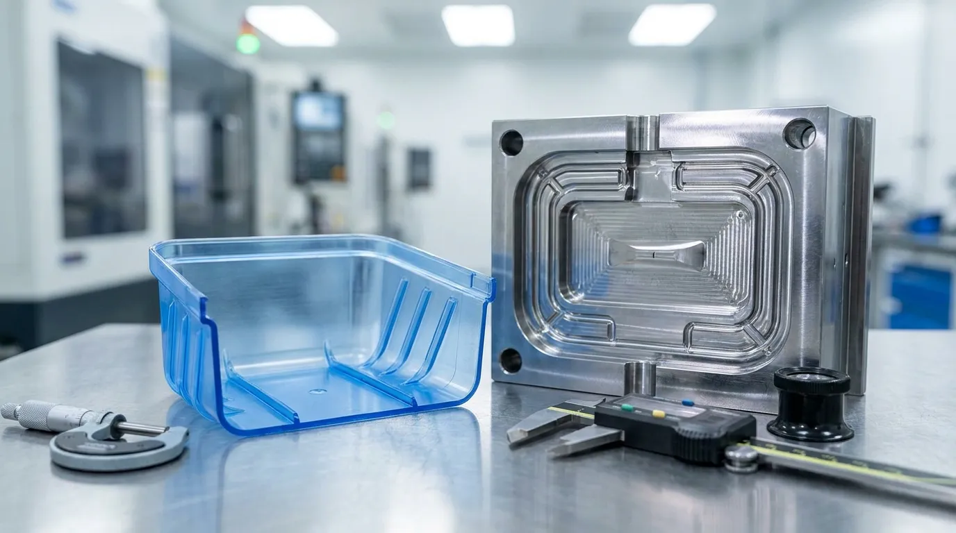
Medical device plastic injection molding works best when part design decisions happen before tooling starts. Engineers should focus on wall thickness, draft angles, sterilization compatibility, tolerances, and moldability early in development. Small geometry changes can prevent tooling revisions, validation delays, production defects, and unnecessary manufacturing costs later in the process.
Medical molded parts have far less room for design mistakes than consumer products. A feature that looks acceptable in CAD can still create warping, flash, sterilization failures, or tooling delays once production begins. This guide focuses on practical design decisions before mold manufacturing starts, so engineering teams can reduce risk and move into validation with fewer surprises.
What makes medical device plastic injection molding design different?

Medical device plastic injection molding requires stricter design control than standard consumer molding because geometry, material choice, sterilization compatibility, and validation requirements directly affect safety, compliance, and manufacturability.
Medical products must meet tighter quality expectations than most commercial plastic parts. A small dimensional issue can affect assembly, sterility, fluid flow, or patient safety. That changes how engineers approach geometry, tolerances, and material selection from the beginning.
The regulatory side also affects design decisions. The FDA medical device framework and quality systems such as ISO 13485 increase the importance of process consistency and documentation. Molded parts need repeatable performance, not just successful prototypes.
Medical parts also face sterilization exposure that consumer products rarely encounter. Steam, radiation, or chemical sterilization can weaken plastics, distort geometry, or shorten product lifespan if the wrong resin is selected.
| Consumer Plastic Part | Medical Molded Part |
|---|---|
| Cosmetic quality focused | Validation and safety focused |
| Moderate tolerance expectations | Tight dimensional consistency |
| Lower documentation requirements | Strict process documentation |
| Limited sterilization exposure | Repeated sterilization exposure |
| Faster design changes | Controlled engineering revisions |
If your team still needs broader tooling knowledge, Sunshine Pro’s complete mold component guide explains the larger injection mold engineering process in more detail.
You can also review the broader medical device molding process before finalizing tooling decisions.
How do you know if a medical part is actually moldable?
A medical plastic part is considered moldable when its geometry supports consistent filling, ejection, dimensional stability, and validation without requiring excessive tooling complexity or repeated secondary operations.
Many medical parts fail during tooling because the original CAD model was designed around appearance or assembly first, then manufacturability second. A design can look clean on screen but still create sink marks, short shots, or difficult ejection once production begins.
The easiest way to evaluate moldability is to review geometry before tooling approval. Engineers should check wall transitions, undercuts, draft angles, gate placement, and cooling behavior early. Small adjustments during DFM review are far cheaper than modifying hardened tooling later.
Features that commonly create tooling problems
Several features increase mold complexity quickly:
- Deep undercuts requiring side actions
- Sharp internal corners
- Sudden wall thickness transitions
- Flat surfaces without draft
- Thin ribs attached to thick walls
- Cosmetic surfaces hiding gate locations
A reusable surgical handle is a common example. The prototype may look correct during 3D printing, but once injection molding begins, missing draft angles can create ejection damage and surface drag marks. That often forces expensive tooling revisions after steel cutting has already started.
Complex undercuts and cosmetic geometry are not always the best choice for medical products. They may look acceptable in CAD, but they frequently increase tooling risk without improving device performance.
| Moldability Check | Why It Matters |
|---|---|
| Uniform wall thickness | Reduces warping and sink marks |
| Proper draft angle | Supports smooth ejection |
| Limited undercuts | Reduces tooling complexity |
| Stable parting line | Improves dimensional repeatability |
| Accessible gate location | Improves filling consistency |
For a broader overview of tooling structure, review these injection mold basics before finalizing production tooling.
Which medical-grade plastics work best for molded parts?
The best plastic depends on the device’s sterilization method, durability requirements, chemical exposure, and regulatory needs. Polycarbonate, polypropylene, polyethylene, and PEEK are among the most common medical injection molding materials.
No single resin works for every medical application. Some plastics handle repeated sterilization well but cost more. Others reduce material cost but struggle with dimensional stability or long-term chemical exposure.
A disposable diagnostic housing, for example, may use polypropylene because it balances chemical resistance and cost. A reusable surgical component may need PEEK or polycarbonate to survive repeated sterilization cycles and mechanical stress.
A successful prototype does not automatically mean the design is production-ready. Some materials perform well during testing but lose strength or discolor after repeated sterilization exposure.
| Material | Best Use | Sterilization Compatibility | Main Limitation |
|---|---|---|---|
| Polypropylene (PP) | Disposable devices | Good | Lower stiffness |
| Polycarbonate (PC) | Surgical housings | Good | Stress cracking risk |
| Polyethylene (PE) | Tubing and fluid systems | Moderate | Lower heat resistance |
| PEEK | High-performance devices | Excellent | Higher cost |
| PVC | Flexible medical parts | Moderate | Regulatory restrictions |
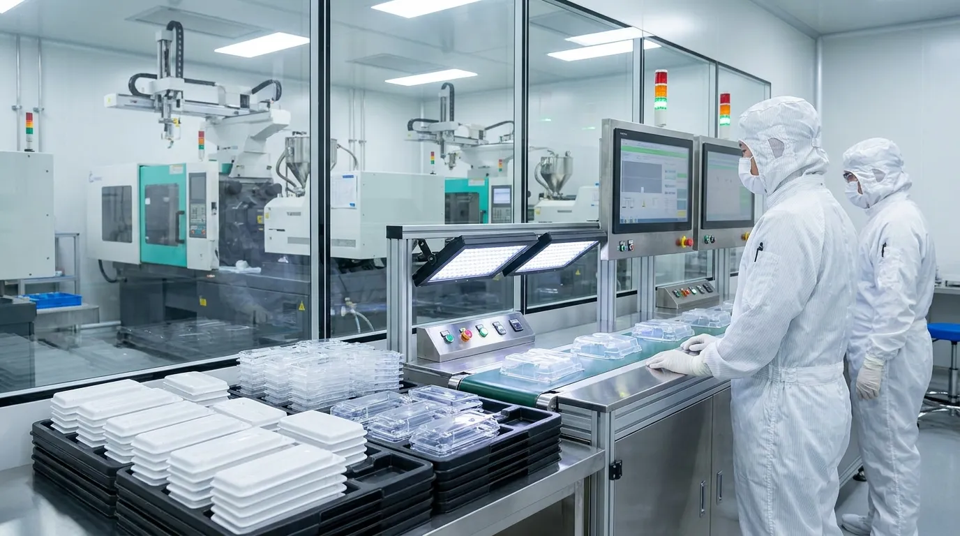
Material selection should also match manufacturing conditions. Clean room molding, chemical exposure, and long production runs all affect resin performance over time.
For more production context, Sunshine Pro’s guide to medical molding materials explains how different medical plastics behave during manufacturing.
How do sterilization requirements change part design?
Sterilization requirements directly affect resin selection, wall thickness, and long-term dimensional stability. A part that survives prototyping may still fail after repeated steam, radiation, or chemical sterilization cycles.
Sterilization affects more than material strength. It can change color stability, surface finish, flexibility, and dimensional accuracy over time. Engineers should evaluate sterilization early instead of treating it as a final production step.
Steam sterilization creates high heat exposure. Gamma radiation can weaken certain plastics. Chemical sterilization may create stress cracking in materials that already carry internal molding stress.
A disposable diagnostic housing offers a good example. One design used uneven wall thickness near a mounting feature. The part molded correctly during testing but warped after gamma sterilization because cooling behavior and shrinkage were inconsistent across the geometry.
| Sterilization Method | Design Concern | Recommended Focus |
|---|---|---|
| Steam sterilization | Heat distortion | Heat-resistant materials |
| Gamma radiation | Material brittleness | Radiation-stable resin |
| Chemical sterilization | Stress cracking | Chemical compatibility |
| EtO sterilization | Venting and residues | Geometry accessibility |
Engineers should also avoid late-stage sterilization changes. Switching sterilization methods after tooling approval often creates expensive redesign work.
What wall thickness and draft angle rules reduce molding problems?
Consistent wall thickness and proper draft angles reduce warping, sink marks, flash, and ejection damage. Small geometry changes early in design often prevent expensive tooling modifications later.
Wall thickness controls how plastic cools and shrinks inside the mold. Large thickness differences create uneven cooling, which often leads to warping, sink marks, or dimensional variation.
Draft angles help the part release from the mold cleanly. Without enough draft, molded parts can drag across steel surfaces during ejection. That damages cosmetic finishes and increases cycle instability.
Common geometry mistakes in medical parts
- Thick bosses connected to thin walls
- Zero-draft cosmetic surfaces
- Sharp internal corners
- Deep ribs without proper support
- Abrupt wall thickness transitions
A catheter component redesign showed how small geometry changes can improve manufacturability. The original design used deep side actions and tight corner transitions. After simplifying the geometry and improving draft angles, the manufacturer reduced tooling lead time and improved molding consistency.
| Geometry Rule | Recommended Practice |
|---|---|
| Wall thickness | Keep as uniform as possible |
| Draft angle | Add draft to all vertical faces |
| Corner radius | Use smooth transitions |
| Rib thickness | Keep thinner than adjacent wall |
| Boss design | Avoid thick material buildup |
If you need deeper tooling context, Sunshine Pro’s guide to mold component design explains how part geometry affects mold performance.
How tight should tolerances really be for medical molded parts?
Not every medical molded feature requires ultra-tight tolerances. Over-constraining dimensions increases tooling complexity, inspection costs, and production risk without always improving device performance.
Many engineering teams apply tight tolerances across entire parts instead of focusing on critical dimensions. That approach increases tooling cost and slows production without adding functional value.
Critical dimensions should receive tighter control because they affect assembly, sealing, fluid flow, or patient safety. Cosmetic or non-functional features usually do not need the same tolerance level.
A reusable medical enclosure showed this clearly during production planning. The original drawing specified ±0.02 mm tolerances across several non-critical features. The tighter limits increased tooling complexity and inspection time but did not improve product function. Relaxing those dimensions simplified manufacturing and reduced production risk.
Tighter tolerances are not always safer in medical molding. Excessive dimensional restrictions can actually increase molding instability by narrowing acceptable processing windows.
| Feature Type | Recommended Tolerance Strategy |
|---|---|
| Sealing surfaces | Tight control |
| Assembly interfaces | Moderate to tight |
| Cosmetic features | Moderate control |
| Non-functional surfaces | Standard molding tolerance |
| Thin flexible sections | Material-dependent review |
Material shrinkage also matters. Polypropylene, polycarbonate, and PEEK behave differently during cooling. Tolerance decisions should match actual molding behavior instead of CAD assumptions.
Long production runs can also create dimensional wear inside tooling. Sunshine Pro’s guide to precision mold wear control explains how mold wear affects long-term consistency.
Which design mistakes cause molding defects in medical parts?
Many medical molding defects begin with avoidable design decisions. Uneven walls, sharp corners, poor gate placement, and unrealistic tolerances often create quality problems before production even begins.
Defects are often blamed on processing conditions, but part geometry usually creates the root problem. Poor cooling balance, difficult filling paths, and unstable ejection commonly trace back to early design decisions.
Medical parts are especially sensitive because validation requirements leave less room for process variation. A geometry problem that might be acceptable in consumer molding can become a major quality issue in regulated production.
| Defect | Common Design Cause |
|---|---|
| Sink marks | Thick wall sections |
| Warping | Uneven cooling |
| Flash | Poor shutoff geometry |
| Short shots | Thin flow paths |
| Weld lines | Poor gate placement |
A medical startup experienced a validation delay after selecting material late in the tooling process. The original mold design worked for one resin family but created filling instability after the material switch. That forced redesign work during validation instead of before tooling approval.
Tool durability matters as well. Repeated molding stress, abrasive resins, and tight shutoffs increase wear over time. Sunshine Pro’s guide to mold durability factors explains how tooling performance affects long-term molding stability.
What should engineers confirm before medical mold manufacturing starts?
Teams should finalize manufacturability decisions before steel cutting begins. Once tooling enters production, even small design changes can increase lead times, validation work, and tooling cost.
The most important step is aligning product engineering, tooling, and manufacturing requirements before approvals are signed. Material selection, sterilization strategy, gate placement, and tolerance expectations should all be reviewed together.
Medical Part Moldability Checklist
| Pre-Tooling Review Item | Status Check |
|---|---|
| CAD geometry finalized | □ |
| Draft angles confirmed | □ |
| Uniform wall thickness reviewed | □ |
| Sterilization method approved | □ |
| Resin selection finalized | □ |
| Tolerance strategy reviewed | □ |
| Gate location evaluated | □ |
| Validation requirements documented | □ |
| Parting line approved | □ |
| DFM review completed | □ |
Information your mold manufacturer needs before tooling approval
Before tooling starts, provide:
- Final CAD files
- Material specification
- Sterilization requirements
- Expected production volume
- Cosmetic surface requirements
- Validation expectations
- Critical dimensions and tolerances
Late-stage changes create some of the biggest delays in medical injection molding projects. A material revision or geometry update after tool steel is cut can add weeks to the production schedule.
Teams preparing for production can review Sunshine Pro’s medical tooling preparation process to better align engineering and manufacturing expectations.
What to Do Next
Medical device plastic injection molding works best when manufacturability drives design decisions from the start. Small geometry adjustments, realistic tolerances, and early sterilization planning can prevent expensive tooling changes later.
Before approving a mold build, review the part from both an engineering and production perspective. Ask whether every feature truly improves function, or simply increases tooling complexity. A cleaner, more stable design usually shortens validation time and improves long-term production consistency.
If your team is still evaluating tooling strategy, material selection, or mold engineering details, use the broader injection mold guides from Sunshine Pro to support the next phase of development.
Frequently Asked Questions
What plastics are commonly used in medical injection molding?
Polycarbonate, polypropylene, polyethylene, PEEK, and PVC are commonly used in medical injection molding because they offer different balances of durability, chemical resistance, sterilization compatibility, and biocompatibility. The best option depends on the device application and regulatory requirements.
How long does it take to make a medical injection mold?
Production mold timelines commonly range from eight to twenty weeks depending on part complexity, validation requirements, cavity count, and tooling revisions. Design changes during tooling development often create the biggest delays.
Why is DFM important in medical injection molding?
DFM helps engineers identify geometry, tolerance, and tooling risks before manufacturing begins. Early DFM review reduces mold revisions, production defects, and validation delays.
Can sterilization damage injection molded medical parts?
Yes. Some plastics lose strength, discolor, warp, or crack after repeated steam, radiation, or chemical sterilization exposure. Material selection and wall design should account for sterilization early in development.
What causes warping in medical molded parts?
Warping is commonly caused by uneven wall thickness, poor cooling balance, sharp geometry transitions, or material shrinkage variation. Consistent geometry usually improves dimensional stability.
Are tighter tolerances always better for medical parts?
No. Excessively tight tolerances increase tooling complexity, inspection costs, and molding instability. Critical dimensions should receive tighter control while non-critical features should remain manufacturable.
Share:


Written By miashuvo
NEWS
GET SERVICE
With quality parts to meet every budget and friendly staff trained to make your visit informative and hassle free.