


Core Pins in Injection Molding: How They Form Holes and Internal Features
Core pins injection molding systems use precision pins to create holes, slots, and internal features inside plastic parts. Molten resin flows around the pin during injection, leaving a finished void after cooling. Proper pin material, support, cooling balance, and tolerance control help prevent flash, hole distortion, premature wear, and molded part defects. Stainless steel and carbide are common choices depending on resin type and production demands.
Small mold components often decide whether a molded part runs smoothly in production or creates constant quality problems. Core pins are a good example. A poorly supported pin can bend, wear out early, or produce inconsistent holes after thousands of cycles. A well-designed pin improves dimensional accuracy, extends mold life, and reduces downtime. Understanding how these pins work helps engineers and buyers avoid expensive tooling mistakes before production starts.
What are core pins in injection molding?
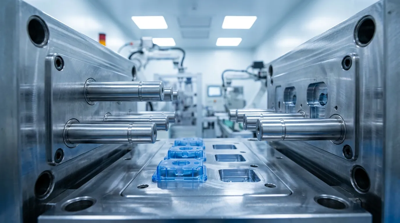
Core pins in injection molding are precision mold components used to create holes, slots, and internal features inside plastic parts. They stay fixed inside the mold while molten plastic flows around them during injection and cooling.
Core pins are usually installed inside the mold core or cavity area. Their job is simple: occupy space where plastic should not exist. When the part cools and ejects, the empty space left behind becomes a finished internal feature. According to DME, these pins are commonly used for precision molding applications where dimensional control matters.
Most core pins are made from hardened tool steel, stainless steel, or tungsten carbide. The material depends on the resin being molded, expected production volume, and wear conditions. Glass-filled plastics, for example, can wear standard steel quickly because of their abrasive filler content.
Manufacturers also vary the shape and geometry depending on the part design. Some pins form simple round holes, while others create complex internal channels or narrow slots. High-volume molds often use replaceable precision core pins so worn pins can be swapped without rebuilding the entire mold.
How do core pins form holes and internal features?
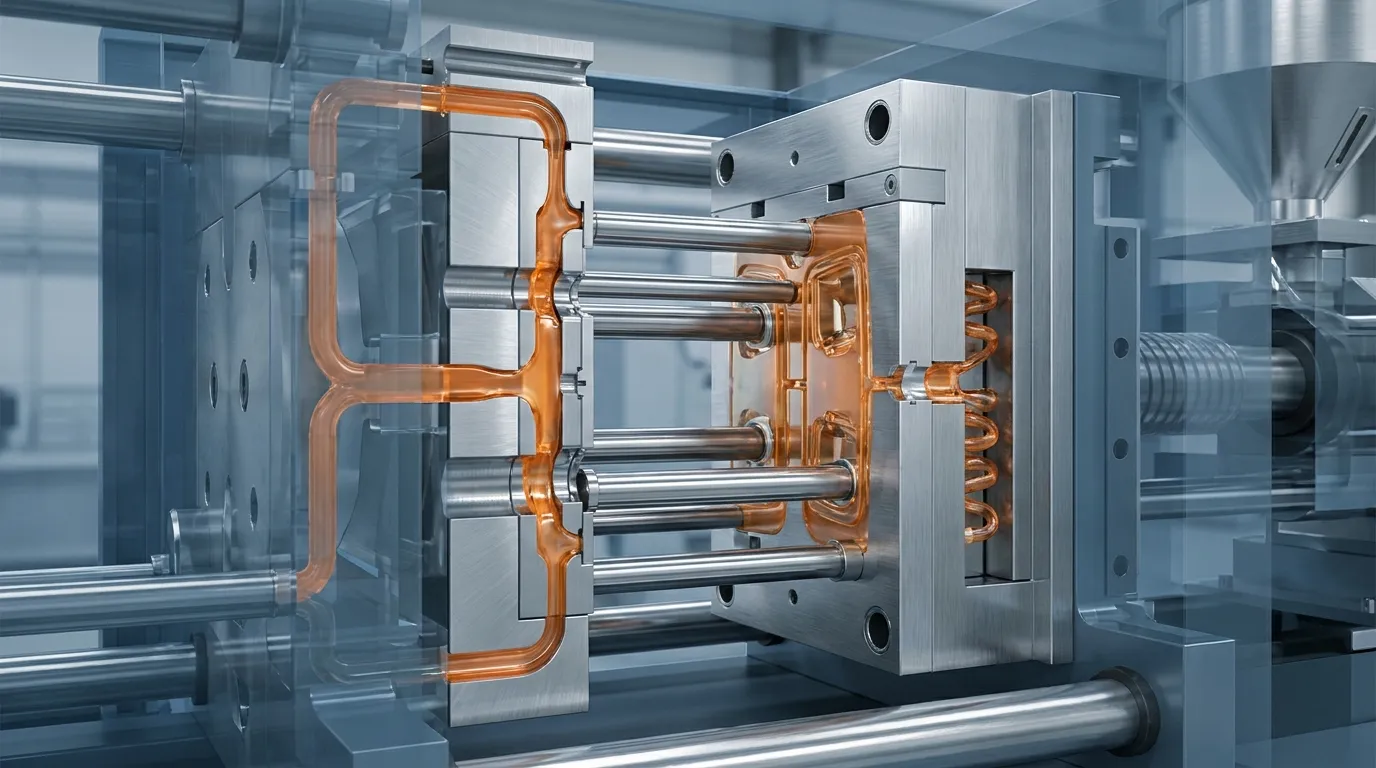
Core pins create internal geometry by occupying space inside the mold cavity while molten plastic flows around them. After cooling, the remaining void becomes the finished hole, channel, or internal feature in the molded part.
The molding cycle starts when the mold closes and molten resin enters the cavity under pressure. The core pin blocks plastic from filling a specific area. Resin flows around the pin surface instead, shaping the surrounding geometry during injection and packing. Electronics Media explains that this process is essential for creating internal molded features without secondary machining.
During injection and packing
Pressure inside the cavity can become extremely high, especially in thin-wall parts or glass-filled materials. If the pin is too thin or unsupported, it may deflect slightly during injection. That small movement can create oval holes, dimensional drift, or uneven wall thickness.
This problem appears often in connector housings and medical parts with micro-features. A medical housing mold using thin carbide pins may hold tight tolerances successfully, but only if the pin length and support geometry are balanced carefully.
During cooling and ejection
Cooling also affects final hole quality. Uneven heat transfer around the pin can cause shrinkage differences in the molded plastic. Some molds add support sleeves or optimized cooling channels to stabilize temperatures around long pins.
After cooling, the mold opens and the part ejects. The core pin must release cleanly without dragging or sticking. If resin shrinks too tightly around the pin, ejection force rises and surface damage becomes more likely.
Which materials are used for core pins?
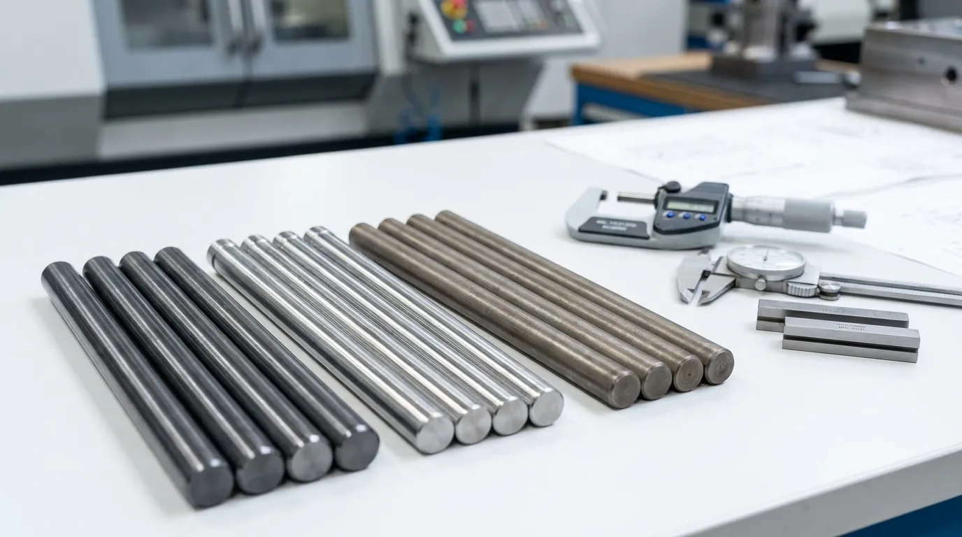
Core pin material selection depends on resin abrasiveness, corrosion exposure, and tolerance requirements. Stainless steel works well for corrosive environments, while carbide performs better in high-wear applications such as glass-filled plastics.
Different molding conditions place different stresses on a core pin. Heat cycling, injection pressure, resin chemistry, and abrasive fillers all affect pin life. Choosing the wrong material can shorten maintenance intervals dramatically.
A standard tool steel pin may work perfectly for low-volume consumer parts. The same pin could wear rapidly in an automotive mold running glass-filled nylon 24 hours a day. Falcon CNC Swiss highlights carbide as a strong option for high-wear molding environments.
| Material | Best Use Case | Main Advantage | Main Limitation |
|---|---|---|---|
| Tool steel | General molding | Cost-effective | Lower wear resistance |
| Stainless steel | Corrosive resins | Corrosion resistance | Less wear resistance than carbide |
| Tungsten carbide | Glass-filled resins | Excellent wear resistance | Higher cost |
Carbide is not always the best option. It performs well in abrasive applications, but stainless steel is often safer for corrosive resin systems. PVC and flame-retardant materials can attack standard steels over time, especially in humid production environments.
A high-volume bottle cap mold is one practical example. Switching from stainless to carbide pins may extend maintenance intervals significantly when abrasive additives increase wear rates. Still, carbide becomes harder to justify for low-volume molds with moderate tolerances.
For molds requiring specialized geometries, many manufacturers use custom mold pins designed specifically for the part shape and resin type.
What problems can poor core pin design cause?
Poor core pin design can cause dimensional drift, flash, warped holes, sticking parts, and premature pin failure. Thin unsupported pins and incorrect material selection are common causes of molding quality problems.
Core pins directly affect molded part quality because they control internal geometry. Even minor pin movement during injection can create visible defects or tolerance issues. Cooling imbalance around the pin may also distort the surrounding plastic.
A consumer electronics housing is a common example. If a long unsupported pin sits near uneven cooling zones, the finished hole may become slightly oval after shrinkage. That small defect can create assembly problems later.
UPMold cooling design guidance shows how cooling imbalance contributes to warpage and dimensional inconsistency during molding.
Core Pin Failure Troubleshooting Table
| Problem | Likely Cause | Pin Condition | Recommended Fix |
|---|---|---|---|
| Flash around hole | Pin movement | Loose or worn support | Improve support fit |
| Oval holes | Pin deflection | Long thin pin | Increase diameter or support |
| Sticking during ejection | Excess shrinkage | Surface wear | Polish or coat pin |
| Rapid wear | Abrasive resin | Steel erosion | Upgrade to carbide |
| Burn marks near feature | Poor venting | Heat buildup | Improve venting and cooling |
Very thin pins may create complex geometry successfully, but unsupported long pins increase the risk of deflection during production. High precision tolerances become difficult to maintain once thermal movement and repeated pressure cycles enter the process.
Cooling matters just as much as machining accuracy. Some molds fail dimensional inspections because the thermal balance around the pin changes during long production runs. Better cooling layout often solves the issue faster than tighter machining tolerances.
If molded parts also rely on ejection around internal features, understanding ejector sleeve designs can help reduce sticking and part damage.
Core pins vs ejector pins: what is the difference?
Core pins shape internal features, while ejector pins push finished parts out of the mold after cooling. Core pins usually remain stationary during molding, while ejector pins move during the ejection stage.
These two mold components often get confused because both appear as cylindrical pins inside the tool. Their functions are completely different. Core pins create geometry. Ejector pins remove the finished part from the mold.
Opro-Tech explains that core pins participate directly in cavity shaping, while ejector systems activate only after cooling.
| Feature | Core Pins | Ejector Pins |
|---|---|---|
| Primary function | Form holes/features | Push out molded part |
| Movement | Usually stationary | Moves during ejection |
| Position in cycle | Injection and cooling | Ejection stage |
| Main wear concern | Deflection and abrasion | Repeated sliding |
The distinction matters during mold design reviews. A buyer focused only on ejector placement may overlook critical support requirements for long core pins. That oversight can create expensive tooling corrections later.
For broader tooling comparisons, the mold ejector systems section explains how ejection components interact with molded part release. Engineers comparing different component categories can also review the ejector pin guide for additional tooling details.
What should engineers check before approving a core pin design?
Before approving a core pin layout, engineers should verify support length, material selection, cooling exposure, and expected resin wear conditions. Small design compromises often become production failures after high-volume cycling starts.
Long unsupported pins are one of the biggest warning signs. A small connector feature may look acceptable in CAD, but repeated injection pressure can bend the pin slightly during production. Support sleeves or geometry changes are sometimes safer than pushing tolerance limits too aggressively.
Core Pin Material Selection Matrix
| Resin Type | Wear Level | Corrosion Risk | Recommended Material | Tradeoff |
|---|---|---|---|---|
| Standard PP | Low | Low | Tool steel | Lower cost |
| Glass-filled nylon | High | Low | Carbide | Higher tooling cost |
| Flame-retardant resin | Medium | High | Stainless steel | Faster wear than carbide |
| Medical resin | Medium | Medium | Stainless steel | Good corrosion resistance |
Approval Checklist
- Verify pin diameter against unsupported length
- Review resin abrasiveness and filler content
- Check cooling layout near long pins
- Confirm tolerance expectations with production volume
- Inspect venting around narrow features
- Review replacement accessibility for maintenance
High precision tolerances are meaningless if cooling balance is poor. Some molds achieve excellent machining accuracy initially, then drift during production because heat distribution changes around the core area.
For engineers needing a broader complete mold component overview, the pillar guide explains how core pins interact with cooling systems, cavities, ejectors, and other tooling elements across the full mold structure.
Getting the Next Step Right
Core pins injection molding systems look simple at first, but they influence part quality, tool life, maintenance frequency, and production stability more than many buyers expect. The right pin material and support design can prevent flash, hole distortion, and early wear before production even starts.
If you're reviewing a new mold design, focus on resin type, unsupported pin length, cooling balance, and expected production volume first. Those factors usually matter more than chasing the tightest possible tolerance on paper. For more complex tooling decisions, reviewing the injection mold design guide can help connect core pin choices to the broader mold system.
Frequently Asked Questions
What is a core pin in injection molding?
A core pin is a precision mold component used to form holes, slots, and internal features inside molded plastic parts. It stays inside the cavity while molten resin flows around it during injection and cooling.
What is the difference between a core pin and an ejector pin?
Core pins create internal geometry inside molded parts, while ejector pins remove the finished part from the mold after cooling. Each component works during a different stage of the molding cycle.
What materials are core pins made from?
Core pins are commonly made from tool steel, stainless steel, or tungsten carbide. The best material depends on wear conditions, corrosion exposure, resin abrasiveness, and production volume.
Can core pins cause molding defects?
Yes. Poorly designed or worn core pins can create flash, dimensional variation, sticking issues, and distorted holes. Long unsupported pins are especially vulnerable to movement during injection.
Why do core pins wear out?
Core pins wear out because of repeated heat cycles, resin abrasion, and injection pressure. Glass-filled plastics and corrosive resins usually increase wear rates faster than standard materials.
How accurate are injection mold core pins?
Precision core pins can hold extremely tight tolerances when they are properly supported and cooled. High-precision molds may achieve micron-level consistency depending on the material and production conditions.
Share:


Written By miashuvo
NEWS
GET SERVICE
With quality parts to meet every budget and friendly staff trained to make your visit informative and hassle free.