


Mold Ejector Pins: How to Choose Pins for Smooth Part Release
Mold ejector pins control how molded parts release from the mold after cooling. Choosing the right pin type, material, size, and placement helps prevent sticking, pin marks, warping, and uneven ejection force. Standard pins work for many molds, but sleeve ejectors, coated pins, and optimized layouts improve release performance in high-volume or complex molding applications.
A poorly designed ejection setup can ruin an otherwise good mold. Parts stick, surfaces show stress marks, and production slows down from bent pins or uneven release force. That’s why mold ejector pin selection matters far beyond basic part removal. The right layout protects part quality, reduces downtime, and keeps cycles stable during long production runs.
What do mold ejector pins actually do during part release?
Mold ejector pins push cooled parts off the mold core using controlled force. Correct pin sizing and placement reduce sticking, deformation, stress marks, and uneven release that can damage molded parts or shorten mold life.
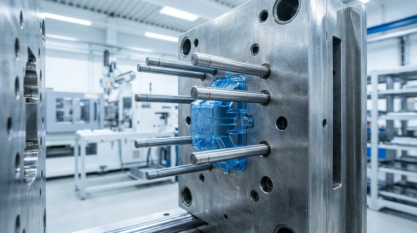
Ejector pins are part of the mold’s ejection system. After the plastic cools and the mold opens, the pins push the part away from the core so it can drop safely or move to the next handling step.
The process sounds simple, but release force has to stay balanced. If too much force concentrates in one area, the part can warp or crack. Poor pin placement can also leave visible circles or white stress marks on finished surfaces.
High-cycle molds depend on stable ejection to maintain consistent production. According to First Mold, ejector systems directly affect release reliability and mold durability during repeated production cycles.
Many manufacturers start by reviewing their overall injection molding ejector systems before adjusting pin layouts for specific parts.
Why does ejector pin placement matter so much?
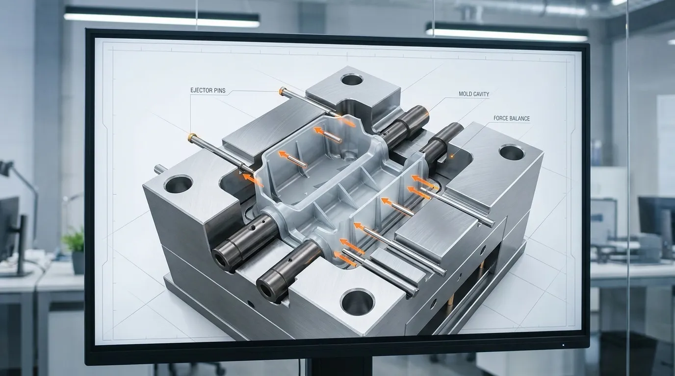
Ejector pin placement matters because uneven release force can warp parts, create white stress marks, or leave visible pin impressions. Pins should support strong structural areas while avoiding cosmetic surfaces and thin unsupported walls.
Placement affects how force travels through the molded part during ejection. Strong ribs, bosses, and thicker sections usually handle ejection pressure better than thin cosmetic walls.
Thin-wall products are especially sensitive. A small electronics housing, for example, may develop whitening near the ejector area if the pin pushes against unsupported plastic. Even when the mold opens correctly, uneven pressure can distort the part during release.
Common areas where parts stick during ejection
Parts often stick around:
- Deep ribs
- Tall cores
- Textured surfaces
- Tight draft angles
- Thin cylindrical features
These areas create more friction during release. According to Aco Mold, balanced ejection helps reduce release resistance and surface defects.
| Part Feature | Common Risk | Better Pin Strategy |
|---|---|---|
| Thin walls | Stress marks | Add wider force distribution |
| Deep ribs | Sticking | Place pins near rib bases |
| Cosmetic surfaces | Visible marks | Move pins to hidden areas |
| Tall cores | Uneven release | Use sleeve ejectors |
| Large flat parts | Warping | Spread pins evenly |
More detailed mold architecture and force distribution topics belong in a broader plastic injection mold basics reference rather than this focused guide.
How do you choose the right mold ejector pin type?
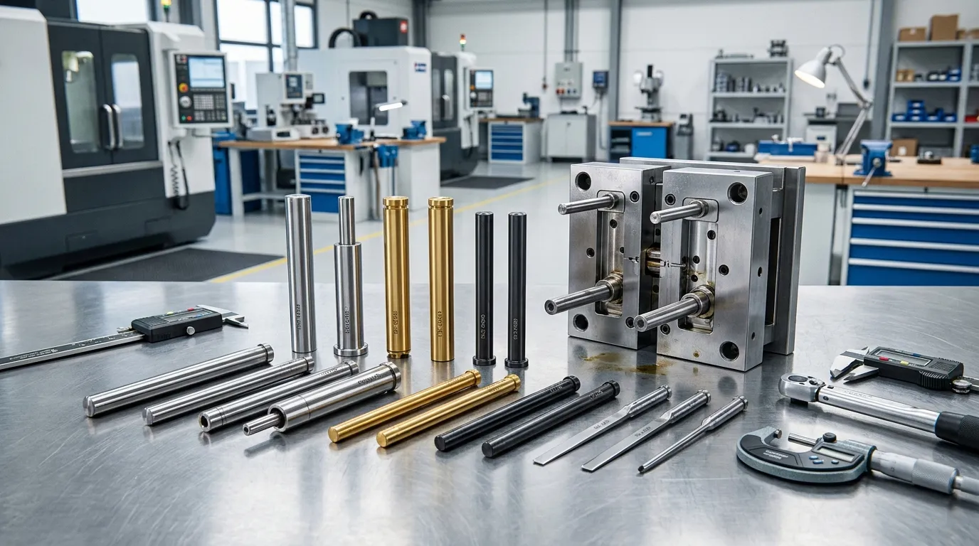
The best mold ejector pin type depends on part geometry, resin behavior, cosmetic requirements, and cycle volume. Standard straight pins handle general molding, while sleeve ejectors, coated pins, and vented designs solve more specialized release problems.
Straight ejector pins work well for many common molds. They’re simple, cost-effective, and easy to maintain. Still, they are not always the safest choice for difficult geometries.
A deep cylindrical cap mold, for example, may deform during release if standard pins apply uneven pressure around the core. In that case, sleeve ejectors distribute force more evenly and reduce distortion risk.
| Ejector Type | Best Use | Main Benefit |
|---|---|---|
| Straight pins | General molds | Simple and economical |
| Sleeve ejectors | Cylindrical cores | Even force distribution |
| Blade ejectors | Thin ribs | Better support in narrow spaces |
| Vented ejectors | Gas-trap areas | Improved air release |
| Coated pins | Abrasive resins | Lower wear and friction |
According to Nonnenmann, ejector pin standards and hardness levels play a major role in long-term mold reliability.
If you need a broader comparison of styles and configurations, this guide to ejector pin types covers additional ejector variations.
Which ejector pin materials and coatings perform best?
Hardened steel ejector pins work for most molds, but DLC or PVD coatings improve wear resistance and reduce friction in high-cycle molds or abrasive resin applications. Material selection should match production volume and resin behavior.
Most standard molds use hardened tool steel ejector pins because they balance strength, wear resistance, and cost. For low-volume production, that’s often enough.
High-cycle molds using abrasive materials create different conditions. Glass-filled resin, for example, increases friction and can wear standard pins faster than many buyers expect. Some mold shops switch to DLC-coated pins to reduce maintenance intervals and extend service life.
When coated ejector pins are worth the extra cost
- Production volume is high
- Resin contains glass fiber or fillers
- Pins move through high-friction areas
- Corrosion resistance matters
- Maintenance downtime is expensive
According to Aco Mold, DLC and PVD coatings can reduce friction and improve wear resistance in demanding molding conditions.
Material selection should also match the broader tooling environment. Many buyers compare ejector materials alongside other precision mold components during mold design reviews.
How many ejector pins does a mold need?
Mold ejector pin quantity depends on part size, wall thickness, geometry, and release resistance. The goal is balanced ejection force with minimal cosmetic impact, not simply adding as many pins as possible.
There’s no universal pin count formula. A small packaging cap may need only a few pins, while a large automotive panel may require a carefully distributed layout across multiple support points.
Adding more pins is not always the correct fix for sticking parts. Poor force balance often creates bigger problems than low pin quantity. Extra pins can also leave more visible marks on finished surfaces.
A multi-cavity packaging mold provides a good example. One mold may release center cavities cleanly while outer cavities stick or warp. In many cases, the issue comes from uneven force distribution rather than insufficient pin count.
Ejector Pin Placement Decision Table
| Mold Condition | Recommended Approach | Main Risk if Ignored |
|---|---|---|
| Large flat part | Spread pins evenly | Warping |
| Thin-wall housing | Support weak sections | Stress whitening |
| Deep core feature | Use sleeve ejector | Distortion |
| High cosmetic finish | Hide pin locations | Visible marks |
| Multi-cavity mold | Balance cavity force | Uneven release |
For a broader overview of mold system planning, many engineers review a complete mold component selection resource before finalizing ejector layouts.
What problems happen when ejector pins are selected incorrectly?
Incorrect ejector pin sizing or placement often causes pin marks, sticking, bent pins, and uneven release force. Most ejection problems come from poor force distribution rather than defective pins alone.
Poor ejector performance usually appears as a visible molding defect first. The part may show circular impressions, white stress marks, distortion, or inconsistent release behavior between cycles.
Long unsupported pins can also bend during production. This often happens when release resistance becomes too high for the selected diameter. Poor alignment or excessive friction increases the problem further.
Why ejector pin marks appear on molded parts
Pin marks happen when pressure concentrates in small areas during release. Cosmetic surfaces, thin walls, and poor cooling conditions make the marks easier to see.
A thin-wall electronics housing is a common example. If pins push near unsupported cosmetic sections, the plastic can whiten or deform during ejection even when molding temperatures remain correct.
Why ejector pins bend during production
Bent pins usually indicate excessive force or poor support. Long slender pins are more vulnerable because they flex under repeated load.
According to Tekwell Machinery, incorrect ejector settings and release timing can also contribute to ejection failures during molding operations.
Ejection Failure Troubleshooting Checklist
| Visible Problem | Likely Cause | Pin-Related Issue | Recommended Fix |
|---|---|---|---|
| Pin marks | Concentrated force | Small contact area | Increase distribution |
| White stress marks | Thin unsupported wall | Poor placement | Move pins to stronger areas |
| Bent pins | Excessive resistance | Undersized diameter | Increase pin support |
| Uneven release | Imbalanced layout | Poor spacing | Rebalance force points |
| Sticking part | High friction | Wrong ejector type | Use sleeve or coated pins |
Many mold shops troubleshoot these issues through detailed ejector pin troubleshooting reviews before redesigning the entire mold.
When should you use sleeve ejectors or special ejector designs?
Standard straight pins handle many molds well, but specialty ejectors solve problems that simple pins cannot. Cylindrical cores, narrow ribs, and trapped air zones often need more specialized solutions.
Sleeve ejectors work best around round cores because they apply force evenly around the feature. They reduce distortion on caps, tubes, and deep cylindrical parts. Blade ejectors support narrow ribs and thin sections where standard round pins would leave concentrated stress.
Vented ejectors help release trapped gas during molding. Air-assisted systems may also improve release in difficult geometries with heavy vacuum or friction conditions.
| Special Design | Best Application | Main Benefit |
|---|---|---|
| Sleeve ejector | Round cores | Even release pressure |
| Blade ejector | Thin ribs | Better narrow support |
| Vented ejector | Gas traps | Improved venting |
| Air assist | High vacuum release | Lower friction |
For more advanced configurations, some mold builders compare additional special ejector solutions before selecting final tooling components.
What should mold buyers confirm before approving ejector pin layouts?
Before approving mold ejector pin layouts, buyers should verify force balance, cosmetic surface protection, maintenance accessibility, and resin compatibility. Early review prevents expensive mold modifications after steel cutting or production startup.
Pin layouts should be reviewed before machining begins. Changes after steel cutting can increase lead times, tooling cost, and production delays.
According to Aprios, mold complexity directly affects production timelines. Catching ejection issues early helps avoid redesign work later.
Buyer Approval Checklist
- Confirm pins avoid cosmetic surfaces
- Check support around thin walls
- Verify balanced force distribution
- Review maintenance accessibility
- Match pin material to resin type
- Confirm support for deep cores
- Check wear risk in abrasive applications
Many buyers also review broader injection mold planning requirements before approving final tooling layouts.
Getting the Next Step Right
Good ejection design protects more than part release. It affects cosmetic quality, mold life, maintenance cost, and cycle consistency across the entire production run. Small pin placement mistakes can create expensive problems once production starts.
The best mold ejector pins setup depends on part geometry, resin behavior, and production volume. Standard pins work well in many molds, but specialty ejectors, better force distribution, and upgraded coatings often improve long-term reliability. Before approving a mold, review the ejection layout carefully and confirm the system fits the actual molding conditions instead of relying on default pin placement.
Frequently Asked Questions
What is an ejector pin in injection molding?
An ejector pin is a hardened metal component that pushes a molded part out of the mold after cooling. It applies controlled force to release the part without damaging the mold or the finished surface.
What causes ejector pin marks on plastic parts?
Ejector pin marks usually appear when force concentrates in small areas or pins are placed on cosmetic surfaces. Poor cooling, insufficient draft angle, or uneven release force can make the marks more visible.
How many ejector pins should a mold have?
The correct number depends on part size, wall thickness, geometry, and release resistance. The goal is balanced force distribution without adding unnecessary visible pin locations.
Which ejector pin material lasts longest?
Hardened tool steel ejector pins usually provide the best durability for high-cycle molding. DLC or PVD coatings can extend service life further in abrasive resin or high-friction applications.
When should sleeve ejectors be used?
Sleeve ejectors work best around cylindrical cores or round features where standard pins cannot distribute force evenly. They reduce distortion risk on tubular and deep-core molded parts.
Why do ejector pins bend during production?
Ejector pins usually bend because of uneven release force, poor alignment, excessive resistance, or unsupported pin length. Incorrect pin diameter selection can also increase bending risk.
Share:


Written By miashuvo
NEWS
GET SERVICE
With quality parts to meet every budget and friendly staff trained to make your visit informative and hassle free.