


Plastic Injection Mold Design: DFM Checklist for Stronger Plastic Parts
Plastic injection mold design depends on good DFM decisions before tooling starts. Consistent wall thickness, proper draft angles, balanced ribs, smooth corner transitions, and clean ejection planning help prevent sink marks, warping, short shots, and mold wear. A practical DFM checklist reduces tooling revisions, improves part strength, and helps manufacturers move into production with fewer delays and quality problems.
A plastic part can look perfect in CAD and still fail during production. Small geometry choices often create sink marks, ejection problems, or expensive tooling changes once steel cutting begins. That’s why DFM, short for design for manufacturability, matters early. This guide walks through the key checks engineers use before approving a plastic part for injection molding, with practical examples you can apply before sending a design to tooling.
What is plastic injection mold design and why does DFM matter?
Plastic injection mold design works best when DFM decisions happen before tooling starts. Wall thickness, draft, ribs, and ejection features directly affect defects, cycle time, tooling complexity, and part consistency.
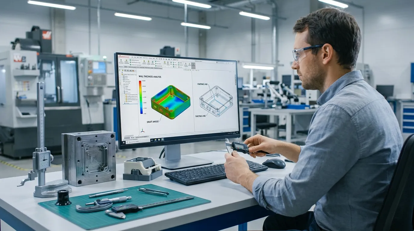
Plastic injection mold design is the process of shaping a part so it can be manufactured reliably inside an injection mold. DFM focuses on reducing production risks before the mold is machined. According to CustomPartNet, geometry choices directly affect cooling behavior, shrinkage, and defect risk during molding.
A strong DFM review looks beyond appearance. Engineers check whether plastic can flow evenly, cool consistently, and eject cleanly from the mold. Even small changes to wall transitions or rib placement can improve part quality and reduce tooling revisions later.
Many product teams wait too long to review manufacturability. That usually increases cost because mold modifications after steel cutting are slower and more expensive than CAD updates early in development.
- Are wall sections consistent?
- Does every vertical face include draft?
- Are ribs sized correctly?
- Will the part eject without scuffing?
- Are undercuts necessary?
If you need a broader tooling overview, review this injection mold design basics guide before moving into detailed DFM checks.
What wall thickness works best for injection molded parts?
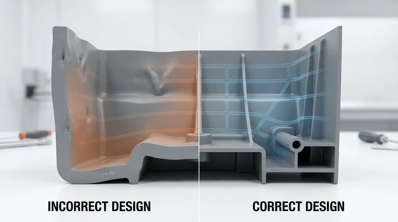
Consistent wall thickness improves plastic flow, cooling balance, and dimensional stability. Thick sections often create sink marks and warping, while abrupt thickness changes increase internal stress and molding defects.
Wall consistency matters more than maximum thickness. Plastic shrinks as it cools, and uneven cooling creates distortion. Thick sections hold heat longer than thin sections, which increases the risk of sink marks and warped geometry.
A common mistake is adding extra wall thickness to improve strength. Thick walls are not always the best solution. In many cases, properly designed ribs create better stiffness with fewer molding defects.
A handheld electronics housing is a good example. One design used ribs that matched full wall thickness. During molding, the rib area cooled unevenly and created visible sink marks on the outer cosmetic surface. Reducing rib thickness solved the issue without reducing strength.
What causes sink marks in thick wall sections?
Sink marks happen when thicker areas shrink more during cooling. Oversized ribs, bosses, and sudden wall transitions usually create the biggest problems.
| Design Condition | Likely Result | Better Approach |
|---|---|---|
| Thick wall sections | Sink marks | Keep wall thickness consistent |
| Sudden wall transition | Internal stress | Use gradual transitions |
| Full-thickness ribs | Surface distortion | Use thinner reinforcing ribs |
| Heavy corner mass | Uneven cooling | Add corner radii |
This mold design considerations resource explains how geometry affects manufacturability across different tooling situations.
Why are draft angles critical for clean part ejection?
Draft angles help molded parts release from the tool without dragging or surface damage. Even small draft improvements can reduce ejection force, cosmetic defects, and mold wear during high-volume production.
Draft creates a slight taper on vertical surfaces so parts can separate from the mold during ejection. Without draft, the plastic drags against the mold wall and increases friction during release.
Zero-draft walls may look acceptable in CAD, but they often create real production problems. Surface scratching, sticking, and ejector stress become more common as cycle counts increase. Protolabs notes that manufacturable geometry improves production consistency and tooling efficiency.
Textured surfaces need even more draft because texture increases contact area inside the mold. A medical enclosure with textured side walls experienced repeated ejection scratches during production testing. Adding draft solved the issue without changing the product appearance.
- Add draft to all vertical walls
- Increase draft on textured surfaces
- Check deep ribs carefully
- Review ejector locations early
- Avoid sharp internal corners
For tight-tolerance products, this precision molding tolerances guide explains how geometry affects dimensional accuracy.
How should ribs and bosses be designed for strength without defects?
Ribs improve stiffness without increasing overall wall thickness when they are properly proportioned. Oversized ribs or unsupported bosses commonly create sink marks, cosmetic distortion, and uneven cooling.
Ribs are one of the safest ways to strengthen a plastic part. They improve stiffness without adding excessive material mass. The key is controlling rib dimensions so cooling remains balanced.
Many cosmetic defects come from oversized ribs hidden behind visible surfaces. Engineers often assume thicker ribs mean stronger parts, but oversized reinforcement usually creates more shrinkage problems during cooling.
Rib thickness guidelines
A practical rule is keeping rib thickness smaller than the surrounding wall section. Balanced geometry improves cooling and reduces visible surface distortion.
| Feature | Recommended Practice | Risk if Ignored |
|---|---|---|
| Rib thickness | Thinner than main wall | Sink marks |
| Rib height | Moderate aspect ratio | Filling issues |
| Rib spacing | Even spacing | Uneven shrinkage |
| Rib corners | Add radii | Stress concentration |
Boss reinforcement mistakes
Bosses often fail because they are unsupported or connected to thick wall sections. A cosmetic packaging cap warped after molding because one side used a heavy reinforced boss design. Redistributing the support ribs balanced cooling and corrected the distortion.
Unsupported bosses can also crack during assembly. Adding gussets or connecting ribs usually improves durability without increasing overall wall thickness.
For complex molded components, this precision molded parts page shows how controlled geometry supports stable production quality.
Which part features increase mold complexity and tooling cost?
Undercuts, deep ribs, sharp corners, and inaccessible geometry often require more complex tooling. These features increase machining time, maintenance requirements, and mold cost while raising defect risk.
Some design features force the mold to include sliders, lifters, or deep core structures. These mechanisms increase mold complexity and usually extend lead time. According to the injection molding process overview, mold geometry directly affects tooling structure and manufacturing difficulty.
Undercuts should only be used when the product function truly requires them. Many cosmetic undercuts add tooling complexity without improving product performance.
An appliance housing is a common example. A late-stage cosmetic undercut required additional side actions inside the mold. That change increased tooling cost and delayed production approval because the mold needed redesign work.
Feature vs Tooling Complexity Table
| Feature | Manufacturing Risk | Cost Impact | Better Alternative |
|---|---|---|---|
| Cosmetic undercut | Side actions required | High | Simplify geometry |
| Sharp corners | Stress concentration | Medium | Add radii |
| Deep narrow ribs | Filling difficulty | Medium | Shorter reinforced ribs |
| Thick bosses | Sink marks | Medium | Gusset support |
| Zero draft walls | Ejection problems | Medium | Add draft taper |
This tooling design process resource explains how geometry choices affect mold engineering decisions.
How do engineers review a plastic part before tooling approval?
A proper injection molding DFM review checks wall consistency, draft, ribs, gates, parting lines, shrinkage, and ejection before steel cutting begins. Early corrections prevent expensive mold modifications later.
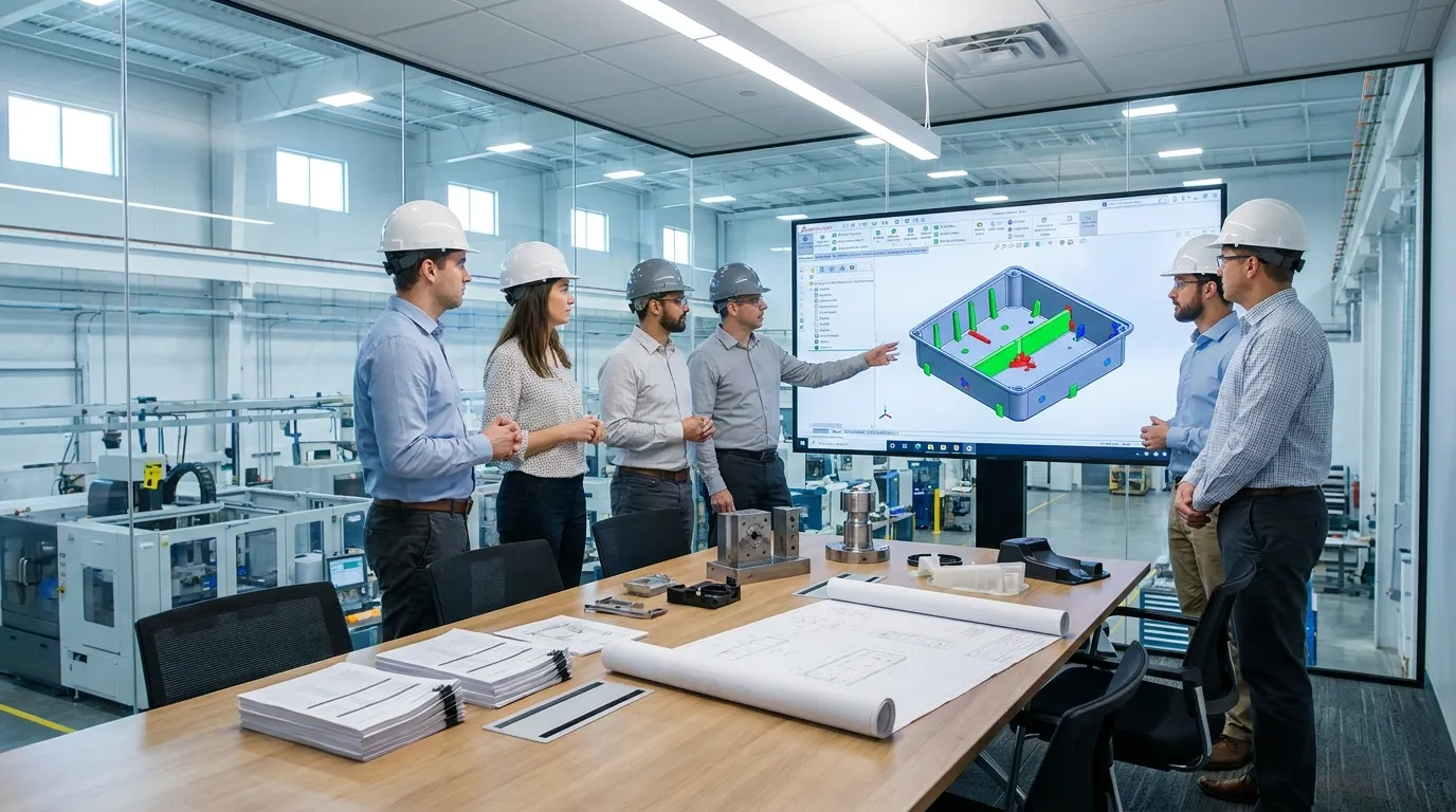
Most engineering teams follow a structured review before releasing tooling for machining. The goal is finding geometry risks before they become manufacturing delays.
A strong DFM process reviews the entire molding cycle, not just the CAD shape. Engineers evaluate how plastic fills the cavity, cools, shrinks, and ejects during production.
Pre-tooling DFM checklist
| Checklist Area | What Engineers Review |
|---|---|
| Wall thickness | Consistency and transition zones |
| Draft | Ejection clearance on all vertical walls |
| Ribs and bosses | Thickness ratios and support structure |
| Corners | Radius and stress concentration |
| Parting line | Mold separation feasibility |
| Gates | Flow balance and cosmetic impact |
| Ejection | Pin locations and release force |
| Undercuts | Need for side actions or lifters |
A product team manufacturing consumer electronics reduced tooling revisions by running this review before steel cutting. The team identified uneven wall transitions and corrected them in CAD instead of modifying hardened tooling later.
Many manufacturers also use mold flow analysis during this stage. Simulation helps identify filling problems, trapped air, and shrinkage risks before production begins.
For broader process planning, this DFM workflow guide covers additional mold engineering considerations.
If you need a larger manufacturing overview, a complete injection mold guide can help connect DFM decisions with the full tooling lifecycle.
What are the most common DFM mistakes in plastic part design?
Most molding defects come from a small group of repeat design mistakes. These problems usually appear during cooling, ejection, or dimensional inspection after production begins.
One of the most common mistakes is treating CAD appearance as proof of manufacturability. A part can look correct visually while still creating flow imbalance, sink marks, or difficult ejection conditions inside the mold.
Common DFM Troubleshooting Table
| Design Mistake | Production Problem | Better Solution |
|---|---|---|
| No draft | Sticking during ejection | Add draft angles |
| Thick wall sections | Sink marks and warping | Maintain wall consistency |
| Sharp internal corners | Stress concentration | Add radii |
| Oversized ribs | Cosmetic distortion | Reduce rib thickness |
| Unsupported bosses | Cracking during assembly | Add gussets or ribs |
| Excessive undercuts | High tooling cost | Simplify geometry |
This high precision molding overview explains why small geometry adjustments matter for repeatable production quality.
Getting the Next Step Right
Good plastic injection mold design starts long before the mold is machined. Most production problems can be traced back to early geometry decisions involving wall thickness, draft, ribs, or ejection planning. A practical DFM review helps teams catch those risks while changes are still inexpensive.
Before approving tooling, review the part as a manufacturing engineer would. Check cooling behavior, ejection paths, reinforcement geometry, and mold complexity together. Small adjustments during design often prevent major tooling revisions later and help production move faster with fewer defects.
Frequently Asked Questions
What is DFM in injection molding?
DFM in injection molding means designing plastic parts so they can be manufactured efficiently and consistently. It helps reduce defects, tooling changes, cycle time issues, and production cost before tooling begins.
What wall thickness is best for injection molding?
Consistent wall thickness usually performs better than thick sections with large transitions. Balanced walls improve cooling, reduce sink marks, and help maintain dimensional stability during molding.
Why is draft angle important in injection molding?
Draft angles help parts release from the mold without sticking or surface damage. Proper draft reduces ejection force and helps maintain surface quality during production.
What causes sink marks in injection molded parts?
Sink marks usually happen when plastic cools unevenly in thick sections or oversized ribs. Reducing local mass and improving wall consistency helps prevent visible surface depressions.
How do undercuts affect mold cost?
Undercuts often require sliders, lifters, or additional tooling mechanisms. These features increase mold complexity, machining time, maintenance, and production cost.
How do you avoid warping in plastic parts?
Warping is reduced by maintaining uniform wall thickness, balanced cooling, and proper rib placement. Uneven shrinkage is one of the main causes of part distortion.
Share:


Written By miashuvo
NEWS
GET SERVICE
With quality parts to meet every budget and friendly staff trained to make your visit informative and hassle free.