


Injection Mold Design Guide: Practical Rules for Better Mold Performance
The injection mold design guide explains how to build molds that produce stable, defect-free parts by balancing flow, cooling, and ejection. Good design relies on consistent wall thickness, proper draft angles, smart gate placement, and efficient cooling channels. When these rules are ignored, problems like warping, sink marks, and short shots appear, increasing cost and slowing production.
Injection molding looks simple from the outside, but mold design is where most production issues are either prevented or created. A small design decision can affect flow, cooling speed, surface quality, and even whether a part can be ejected cleanly. This guide focuses on practical rules engineers use to avoid defects and keep production stable without constant tool rework.
What actually makes an injection mold design successful?
A successful injection mold design balances flow, cooling, and part ejection so the plastic fills evenly, cools uniformly, and releases without stress or damage. When these three systems work together, defects drop and production becomes stable and predictable.
Good mold design is not about one perfect feature. It is about how all elements interact under heat and pressure. If flow is uneven, you get weld lines or air traps. If cooling is inconsistent, parts warp. If ejection is poorly planned, parts stick or crack.
Most production failures trace back to imbalance. For example, fast filling without proper cooling creates internal stress. Or perfect geometry fails because the part cannot release cleanly from the mold surface.
A practical way to judge success is simple: the mold should run long cycles with minimal adjustment, low scrap rate, and consistent part quality across batches. If constant tuning is needed, the design is not stable yet.
How should you structure an injection mold design process step-by-step?
Start injection mold design by analyzing part geometry, then define flow and gating, followed by cooling layout, and finally ejection and structural support. This sequence reduces redesigns and prevents costly tooling changes later.
A structured process avoids guessing and rework. Most experienced engineers follow a predictable order because each step depends on the previous one.
First, you study the part shape, thickness, and functional surfaces. This defines what is possible in molding. Next comes flow planning, where you decide how molten plastic will enter and fill the cavity. After that, cooling channels are designed to control solidification speed. Finally, you design ejection points and mechanical support.
Decision Flowchart
| Step | Question | Output |
|---|---|---|
| 1 | Is the part geometry moldable? | Design adjustment or approval |
| 2 | Where should plastic enter? | Gate location plan |
| 3 | How will flow fill evenly? | Flow path design |
| 4 | How will heat be removed? | Cooling layout |
| 5 | How will part exit safely? | Ejection system |
Skipping steps or mixing order usually leads to redesign loops. A well-structured process keeps tooling cost predictable and reduces trial-and-error after manufacturing starts.
Internal link: molding service overview
What wall thickness rules prevent defects in molded parts?
Uniform wall thickness is the most important rule in mold design because uneven sections cool at different rates, causing warping, sink marks, or internal stress. Most thermoplastics work best in a consistent 1.2–3 mm range.
When plastic cools, it shrinks. If one section is thicker than another, it shrinks slower and pulls the surrounding material unevenly. That’s what creates sink marks or warping.
Designers avoid this by keeping walls as consistent as possible. If thickness changes are unavoidable, transitions should be gradual, not sudden. Sharp changes create stress points that show up later in production.
Ribs are often used instead of thick walls. This keeps strength without creating uneven cooling zones. It is a simple shift in design thinking that prevents many common defects before they even appear.
How do draft angles affect mold release and surface quality?
Draft angles allow molded parts to release smoothly from the mold. Without them, parts stick, scratch, or deform during ejection, especially in deep or textured cavities.
Even a perfectly molded part becomes useless if it cannot exit the mold cleanly. Draft angles solve this by slightly tapering vertical walls so the part separates without friction.
Typical designs use around 1–2 degrees of draft. However, deeper cavities or textured surfaces need more. Smooth polished surfaces may need less, but skipping draft entirely is rarely safe.
Poor draft design increases ejection force, which can damage both the part and the mold. Over time, it also wears down tooling surfaces, reducing mold life and consistency.
Where should you place gates for optimal flow control?
Gate placement controls how plastic flows into the cavity, and it directly affects weld lines, air traps, and surface quality. The goal is balanced filling with minimal visible defects.
If the gate is placed poorly, the material may meet unevenly, forming weak weld lines. It can also trap air in corners or create uneven pressure across the part.
A good gate location allows the cavity to fill in a controlled, symmetrical way. This reduces stress points and improves both strength and appearance. Designers also avoid placing gates on visible cosmetic surfaces unless necessary.
Gate design is not just about entry point, but about flow direction. A small change in position can completely change how the part fills and cools.
Internal link: custom molding solutions
How can ribs and bosses strengthen parts without defects?
Ribs and bosses reinforce parts without increasing wall thickness, which helps prevent sink marks while maintaining structural strength.
Instead of making a wall thicker, ribs distribute strength across a structure. This keeps cooling uniform and avoids thick sections that cool slowly.
However, rib design must be controlled. If ribs are too thick or too close to outer walls, they create sink marks on the surface. Bosses used for screws or fittings follow similar rules.
A common design approach is to keep ribs thinner than the main wall and spaced properly. This ensures strength without compromising surface quality or dimensional stability.
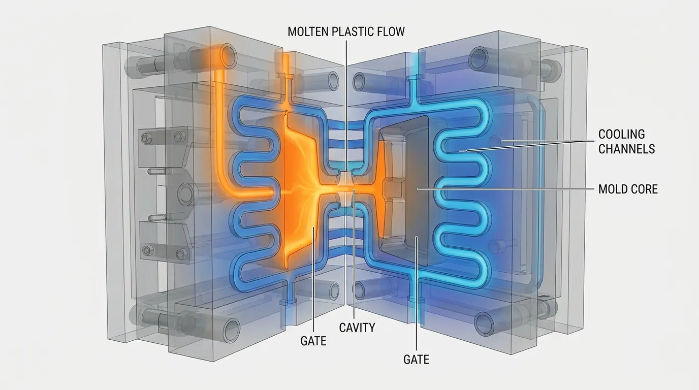
How does cooling system design control cycle time and quality?
Cooling design controls how quickly and evenly a part solidifies, which directly affects cycle time, warping, and final quality. Poor cooling leads to uneven shrinkage and unstable production.
Cooling channels remove heat from molten plastic after it fills the cavity. If cooling is uneven, some areas shrink faster than others, creating distortion.
Well-designed cooling systems reduce cycle time while improving consistency. This is especially important in high-volume production where small delays add up quickly.
Hot spots inside thick sections are a common problem. Proper channel placement helps eliminate them and keeps temperature distribution balanced.
Internal link: precision molding
How do you validate injection mold design before tooling?
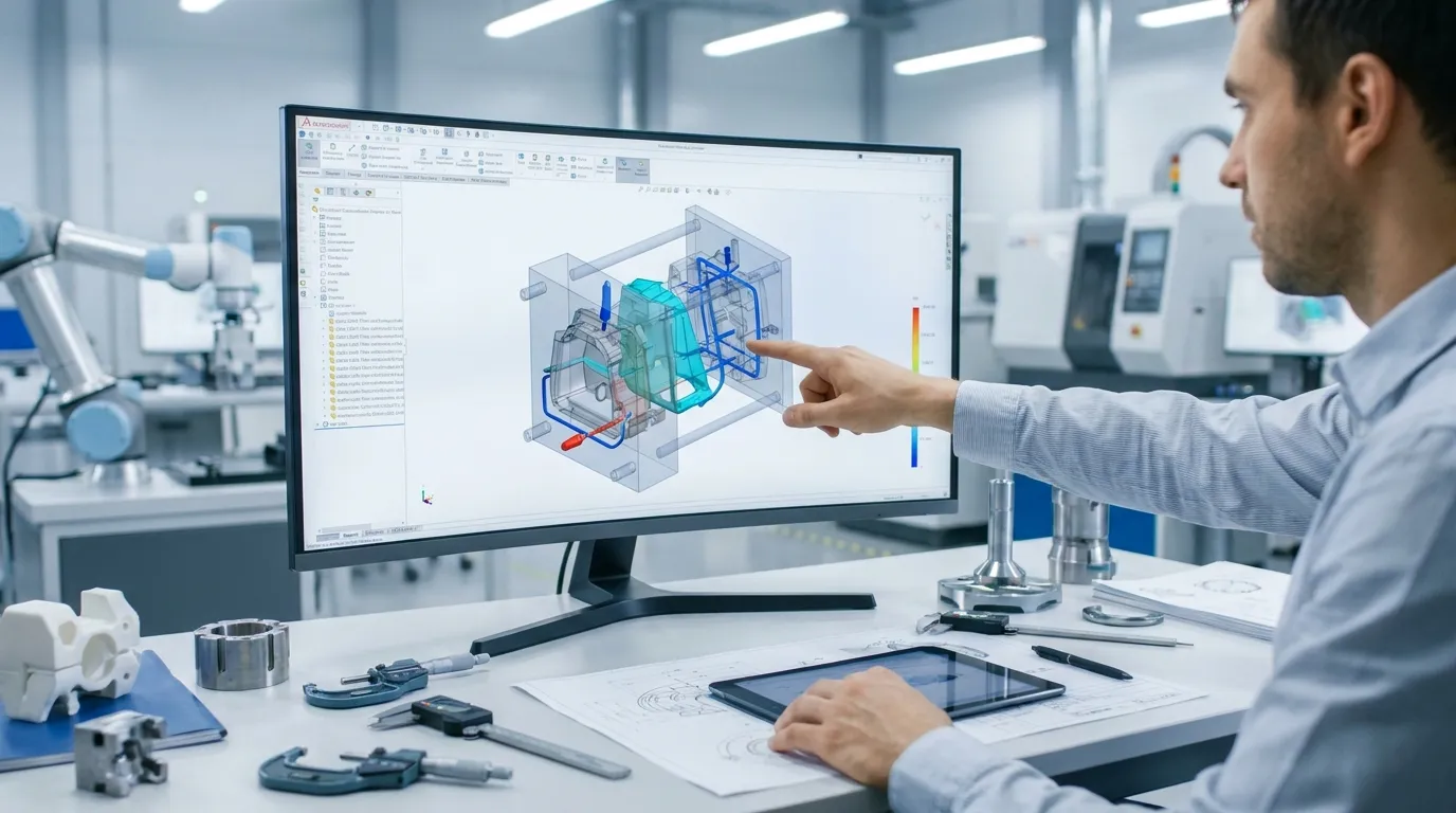
Injection mold design is validated using CAD review, design-for-manufacturing checks, and mold flow simulation before any steel is cut. This reduces risk and avoids expensive tooling changes.
Validation is where design meets reality. Even a well-drawn model can fail if flow behavior or cooling performance is ignored.
Mold flow simulation helps predict how plastic will move, where pressure will build, and where defects may appear. CAD review ensures geometry can actually be manufactured and assembled.
This step is often skipped under time pressure, but it is one of the most cost-saving stages in the entire process.
Internal link: high precision molding
What are the most common injection mold design mistakes?
The most common mistakes include uneven wall thickness, missing draft angles, poor gate placement, and ignoring cooling balance. These issues directly lead to defects and higher production costs.
Sharp corners are another frequent issue because they create stress points and weaken parts. Designers sometimes also underestimate shrinkage behavior, which leads to dimensional errors after cooling.
Another major mistake is focusing only on part shape without considering how it will be manufactured. A design that looks perfect in CAD may fail during real molding if flow and ejection are not planned properly.
Avoiding these mistakes early saves both tooling cost and production time.
Final Thoughts
Good injection mold design is not about adding complexity, it is about removing uncertainty. When flow, cooling, and ejection are designed together, production becomes stable and predictable. The injection mold design guide principles you apply here, like uniform walls, proper draft, smart gating, and balanced cooling, directly determine part quality and cost efficiency.
If you're planning a new project, the next step is reviewing your design against these rules before tooling starts. Small changes at the design stage prevent major issues later in production.
Frequently Asked Questions
What is injection mold design?
Injection mold design is the process of engineering a mold that shapes molten plastic into finished parts. It focuses on flow, cooling, and ejection so parts are produced consistently without defects.
Why is draft angle important in mold design?
Draft angles help parts release from the mold without sticking or damage. Without proper draft, parts can scrape, deform, or increase wear on the mold surface during ejection.
What causes warping in injection molding?
Warping happens when different sections of a part cool at different speeds. Uneven wall thickness or poor cooling design creates internal stress that distorts the final shape.
How thick should injection molded walls be?
Most designs use wall thickness between 1.2 mm and 3 mm depending on material. Keeping thickness consistent is more important than the exact value for preventing defects.
What is the role of gate placement?
Gate placement controls how plastic enters and fills the mold cavity. Poor placement can cause weld lines, air traps, or uneven flow that weakens the part.
Why do sink marks occur in molded parts?
Sink marks form when thick sections cool slower than thin areas. The uneven shrinkage pulls the surface inward, especially near ribs or bosses.
Share:


Written By miashuvo
NEWS
GET SERVICE
With quality parts to meet every budget and friendly staff trained to make your visit informative and hassle free.